Owner’s Manual For professional use only Do not use this equipment before reading this manual! NOTE: This manual contains important warnings and instructions. Please read and retain for reference. 440 ix Airless Sprayer Model Numbers: Skid Skid High High Basic Loaded Rider Basic Rider Loaded Printed in the U. S. A. 700-3030 700-3035 700-3040 700-3045 X-Lock Theft Deterrent System Security Code — — — — 0105 © 2005 Titan Tool Inc. All rights reserved. Form No.
Table of Contents • NEVER allow any part of the body to touch the fluid stream. DO NOT allow body to touch a leak in the fluid hose. • NEVER put hand in front of the gun. Gloves will not provide protection against an injection injury. • ALWAYS lock gun trigger, shut pump off, and release all pressure before servicing, cleaning tip or guard, changing tip, or leaving unattended. Pressure will not be released by turning off the motor.
Grounding Instructions GAS ENGINE (WHERE APPLICABLE) Always place sprayer outside of structure in fresh air. Keep all solvents away from engine exhaust. Never fill fuel tank with a running or hot engine. Hot surface can ignite spilled fuel. Always attach ground wire from pump to a grounded object. Refer to engine owner’s manual for complete safety information. HAZARD: EXPLOSION HAZARD DUE TO INCOMPATIBLE MATERIALS - will cause severe injury or property damage.
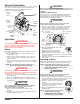
General Description CAUTION This airless sprayer is a precision power tool used for spraying many types of materials. Read and follow this instruction manual carefully for proper operating instructions, maintenance, and safety information. Siphon Tube Return Motor Hose Pressure Control Knob Always use a minimum 12 gauge, three-wire extension cord with a grounded plug. Never remove the third prong or use an adapter.
. Turn on the sprayer by moving the ON/OFF switch to the ON position. 6. Allow the sprayer to run for 15–30 seconds to flush the old solvent out through the return hose and into the metal waste container. 7. Turn off the sprayer by moving the ON/OFF switch to the OFF position. WARNING Ground the gun by holding it against the edge of the metal container while flushing. Failure to do so may lead to a static electric discharge, which may cause a fire. 12.
Menu Screens Solid Yellow When the pressure indicator is solid yellow, the sprayer is operating between 201 and 1900 PSI. A solid yellow pressure indicator means: • The sprayer is at the proper pressure setting for spraying stain, lacquer, varnish, and multi-colors • If the pressure indicator goes to solid yellow when the pressure is set so that it starts at solid green, it indicates one of the following: a. Tip Wear Indicator — when spraying with latex or at high pressure the solid yellow appears.
Service Time Screen Prime Screen The Prime screen appears PRIME when the pressure control knob is set at the “Min” setting in the yellow zone. Pulse Clean Screen The Pulse Clean screen PULSE CLEAN appears when the pressure ACTUAL PSI XXXX control knob is set at the PULSE CLEAN position in the red zone and the PRIME/SPRAY valve is in the PRIME position. SERVICE TIME The Service Time screen MENU-1 allows the user to set a service SELECT-4 time interval (in hours).
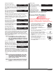
Spraying Overlap edges WARNING POSSIBLE INJECTION HAZARD. Do not spray without the tip guard in place. Never trigger the gun unless the tip is in either the spray or the unclog position. Always engage the gun trigger lock before removing, replacing, or cleaning tip. Spraying Technique The following techniques, if followed, will assure professional painting results. Hold the gun perpendicular to the surface and always at equal distance from the surface.
Cleanup 13. Continue to trigger the spray gun into the waste container until the solvent coming out of the gun is clean. NOTE: For long-term or cold weather storage, pump mineral sprits through the entire system. For short-term storage when using latex paint, pump water mixed with Titan Liquid Shield through the entire system (see the Accessories section of this manual for part number).
Replacing the Motor Replacing the Gears 1. Perform the Pressure Relief Procedure and unplug the sprayer. 2. Loosen and remove the four motor cover screws. Remove the motor cover. 3. At the electronic pressure control (EPC) on the back off the motor, disconnect the wire coming from the potentiometer and the wire coming from the transducer. Also, disconnect the two wires coming from the control panel board (refer to the electrical schematic in the Parts List section of this manual). 4.
Replacing the Transducer Replacing the PRIME/SPRAY Valve 1. Loosen and remove the four front cover screws. Remove the front cover. 2. Stop the sprayer at the bottom of its stroke so that the piston is in its lowest position. 3. Perform the Pressure Relief Procedure and unplug the sprayer. Perform the following procedure using PRIME/SPRAY valve replacement kit P/N 700-258 1. Push the groove pin out of the valve handle. 2. Remove the valve handle and the cam base. 3.
Servicing the Fluid Section Repacking the Fluid Section 1. Remove the foot valve assembly using the steps in the “Servicing the Valves” procedure above. Use the following procedures to service the valves and repack the fluid section. Perform the following steps before performing any maintenance on the fluid section. 1. Loosen and remove the four front cover screws. Remove the front cover. 2. Stop the sprayer at the bottom of its stroke so that the piston is in its lowest position. 3.
Gun Filter 15. Position the pump block underneath the pump housing and push up until it rests against the pump housing. 16. Thread the pump block mounting screws through the pump block and into the pump housing. Tighten securely. 17. Reassemble the foot valve assembly into the pump block. 18. For High Rider cart units, thread the siphon tube into the foot valve and tighten securely. Make sure to wrap the threads on the siphon tube with Teflon tape before assembly.
Troubleshooting Problem The unit will not run. Cause Solution 1. The unit is not plugged in. 2. Tripped breaker. 3. The pressure is set too low (pressure control knob set at minimum setting does not supply power to unit). 4. Faulty or loose wiring. 5. Excessive motor temperature. 6. ON/OFF switch is defective. The unit will not prime. 1. The PRIME/SPRAY valve is in the SPRAY position. 2. Air leak in the siphon tube/suction set. 3. The pump filter and/or inlet screen is clogged. 4.
Troubleshooting Problem Cause Poor spray pattern. Solution 1. The spray tip is too large for the material being used. 2. Incorrect pressure setting. 3. Insufficient fluid delivery. 4. The material being sprayed is too viscous. The unit lacks power. 1. The pressure adjustment is too low. 2. Improper voltage supply. 1. Replace the spray tip with a new or smaller spray tip following the instructions that came with the spray gun. 2.
Consignes de sécurité AVERTISSEMENT AUX MÉDECINS : Une perforation sous-cutanée constitue un traumatisme. Il est important de traiter la blessure de façon chirurgicale aussitôt que possible. NE RETARDEZ PAS ce traitement pour des recherches de toxicité. La toxicité n'est un risque que dans les cas où certains produits de revêtement pénètrent dans le flux sanguin. Il peut être nécessaire de faire appel à des soins de chirurgie plastique ou de reconstruction de la main.
Instructions de mise à la terre MOTEUR À ESSENCE (DANS LES CAS OÙ CELA S’APPLIQUE) Toujours placer la pompe à l’extérieur de la structure à l’air frais. Garder tous les solvants loin de l’échappement du moteur. Ne jamais remplir le réservoir à carburant lorsque le moteur est en marche ou lorsqu’il est chaud ; les surfaces chaudes risquent d’enflammer le carburant déversé accidentellement.
Precauciones de seguridad NOTA PARA EL MÉDICO: La inyección dentro de la piel es una lesión traumática. Es importante que la lesión se trate quirúrgicamente tan pronto como sea posible . NO retrase el tratamiento por investigar la toxicidad. La toxicidad es motivo de preocupación con algunos revestimientos que se inyectan directamente en la corriente sanguínea. Es recomendable consultar a un cirujano plástico o reconstructor de manos.
Instrucciones para conectar a tierra PELIGRO: PELIGRO DE EXPLOSIÓN DEBIDO A MATERIALES INCOMPATIBLES - Podría causar lesiones severas o daños en la propiedad. PARA PREVENIR: • No utilice materiales que contengan blanqueador o cloro. • No use solventes con hidrocarburos halogenados, tales como productos para eliminar el moho, cloruro de metileno y 1,1,1 - tricloroetano. Estos no son compatibles con el aluminio.
Parts List Main Assembly 1 12 2 13 14 3 4 15 5 6 16 7 8 17 18 9 10 11 19 20 21 22 23 24 High Rider Model 20 © Titan Tool Inc. All rights reserved.
5 6 7 8 Part # 704-181 704-232 700-681 704-499 704-553 704-229 704-486 704-488 704-469 9 704-467 10 11 12 704-487 704-300 765-063 704-369 Item 1 2 3 4 Description Quantity Screw (includes washer and grommet) ......4 Motor cover.................................................1 Screw..........................................................4 Power cord (skid)........................................1 Power cord (high rider) Ground screw .............................................1 Screw..............
Fluid Section Assembly (Skid P/N 704-538, High Rider 704-571) Install upper packing with raised lip and O-ring facing down. O-Ring Raised Lip 1 19 2 3 20 4 21 5 22 23 24 6 25 7 8 26 Beveled Edge 9 10 11 Install lower packing with the beveled edge facing up. 12 13 14 15 16 17 18 22 © Titan Tool Inc. All rights reserved.
Item 1 2 3 4 5 6 7 8 9 10 11 12 13 14 15 16 17 18 Part # 730-508 700-587 704-564 704-532 227-006 704-547 704-551 704-557 762-144 704-558 704-587 755-186 700-821 730-510 762-145 762-137 762-058 704-054 730-511 Description Quantity Retainer nut ................................................1 Piston guide ................................................1 Upper packing assembly with tool..............1 Pump block .................................................1 Outlet fitting..............................
Labels High Rider Cart Assembly (P/N 704-574) Part # 313-1638 313-1629 313-1673 313-1847 313-1906 313-2324 313-2327 313-2328 1 Description Front cover label Motor cover label Warning label (injection/explosion) Shock hazard label Infinity motor label X-Lock label Xact Digital Control System label Xact Instruction label 2 3 4 5 Item 1 2 3 4 5 Part # 704-573 704-355 704-354 704-353 710-199 Description Quantity Cart weldment (includes item 5).................1 Cap ......................................
Accessories Synergy Fine Finish Tips • Perfect for all fine finish work • Ideal for lacquers, stain, enamels, urethane, and clear top coats • Increases standard tip life up to 80% • Delivers up to a 27% finer atomization at lower pressures • Increases transfer efficiency resulting in less overspray Part No. Description 671-XXX ..........Synergy Fine Finish Tips Airless Tip Selection Tips are selected by the orifice size and fan width.
Notes 26 © Titan Tool Inc. All rights reserved.
Notes © Titan Tool Inc. All rights reserved.
Warranty Titan Tool, Inc., (“Titan”) warrants that at the time of delivery to the original purchaser for use (“End User”), the equipment covered by this warranty is free from defects in material and workmanship.