
Instructions / Assembly


4.
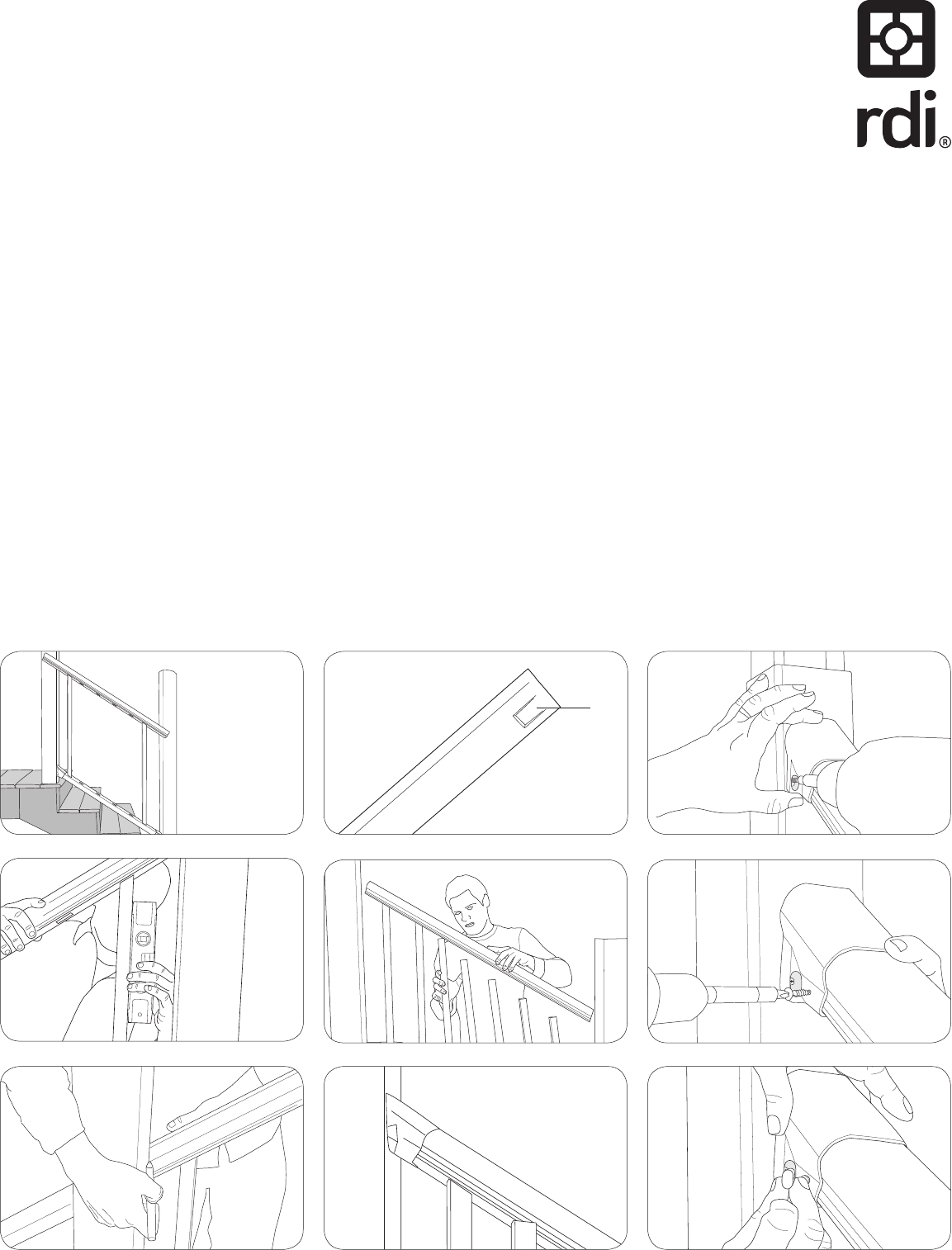
Insert a baluster without a tab (Figure 9
shows notched baluster with tab) into the
rst and last baluster holes of the installed
bottom rail (Fig. 6). Set the top rail in
place by inserting these balusters into the
corresponding holes in the top rail. For ease
of measurement, place the top rail to the
side of the post or mounting surface as in
Figure 6.
Adjust for plumb (Fig. 7) ensuring sufcient
clearance (minimum of 2
5
/
8
" measured
horizontally) between the rst baluster hole
and the post or mounting surface at each
end.
Trace the post or mounting surface onto
each rail end and mark
1
/
8
" short to allow for
expansion (Fig. 8). The rail can now be cut
at these marks.
5.
Insert a baluster into each baluster hole
of the bottom rail. Each kit contains 4 to
6 notched balusters (Fig. 9); space them
evenly throughout each section.
Set the top rail in place by inserting the
rst baluster (at the upper post) into the
corresponding baluster hole of the top rail,
and work toward the bottom (Fig. 10).
6.
Slide a bracket onto each end of the top rail
as shown pointing toward the rail ends (Fig.
11).
Check for proper t and attach to the
mounting surface using the appropriate
mounting hardware (see step 3) for your
application (Fig. 12).
Pre-drill using a
1
/
8
" drill bit and install a
supplied rail set screw through the side of
each bracket to secure the rail in place
(Fig. 13).
7.
Insert button caps (E) over set screws (C)
and snap the bracket plugs (D) in place.
(Fig. 14). If using a Titan steel post, snap
trim rings around bottom ange of support
post. Attach post cap, sold separately,
using vinyl adhesive.
(Fig. 6) (Fig. 9) (Fig. 12)
(Fig. 7) (Fig. 10) (Fig. 13)
(Fig. 8) (Fig. 11) (Fig. 14)
Tab
Notched baluster