
Instruction Manual

HAB Installation Manual
IOM-HAB-00 06-30-04
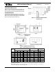
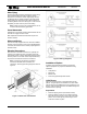
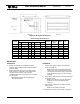
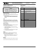
Figure 12. Mixing Box Dimensions
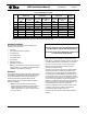
Table 3. Mixing Box Dimensions
Mixing Box Dimensions
Model
A B C D E F
Damper
Ship Wgt.
(lbs)
CFM SP
HAB08 8 16 16 6 2 18 (2) 16 x 8 44 800 0.07
HAB12 8 16 16 6 2 27.5 (2) 26 x 8 49 1200 0.08
HAB16 8 20 16 8 4 29 (2) 28 x 8 53 1600 0.1
HAB20 8 20 16 8 4 36 (2) 34 x 8 63 2000 0.07
HAB30 10 25 18 8 7 45 (2) 44 x 10 101 3000 0.06
HAB40 12 32 20 10 10 48 (2) 46 x 12 120 4000 0.03
HAB60 14 40.25 22 12 14.25 58 (2) 56 x 14 197 6000 0.05
HAB80 14 45 22 15 16 66 (2) 56 x 14 205 8000 0.04
Note: All dimensions in inches.
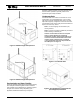
Electric Heat
Preparation
Installation
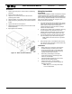
1.
Position heater element section over the blower
wheel of the HAB unit.
Note: Heater baffle must be aligned with the
blower cut-off scroll. Heater should be rotated
180 degrees if necessary to align. This ensures
proper blower discharge of air over the heater
elements.
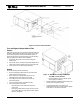
1.
2.
2.
Attach electric heat plenum to unit using #6 or larger
sheet metal screws.
Note: Ensure plenum is securely attached to
HAB unit only and not to blower housing
extension.
Ensure duct materials are compatible for 250º F
operation. Refer to NFPA pamphlet
90A and 90B for
more information.
Ensure ample room exists in the ductwork. Electric
heater must have at least 24 inches of straight duct
clearance before an elbow. If 24 inches are
unavailable, devices such as turning vanes or baffles
may be required.
Note: Electric heaters are incompatible with
discharge equipment.
3.
Add insulation, if necessary, to outside of heater
plenum section.
Note: Do not insulate duct heater.
The following figure shows unit and heater components.
7 of 9