
User Manual

Copyright © 2011, Tjernlund Products, Inc. All rights reserved. P/N 8504067
REV. A 11/11
READ INSTRUCTIONS CAREFULLY
RELAY/TIMER PART NUMBER 950-0014
NON-ADJUSTABLE RELAY/TIMER
OWNERS INSTRUCTIONS
THESE INSTRUCTIONS MUST REMAIN
WITH EQUIPMENT
DO NOT DESTROY
ALWAYS FOLLOW HEATER
MANUFACTURER’S INSTRUCTION
FOR PROPER OPERATION OF
HEATER AND RELIGHTING OF PILOT
PART #950-0014 INSTALLATION INSTRUCTIONS
24-120 VAC INPUT APPROX. 45 SECOND ( + 10% )
NON-ADJUSTABLE POST-PURGE RELAY/TIMER
A) Disconnect 120 VAC Power from the Power Venter before continuing.
B) All wiring from the Power Venter to the appliance must be appropriate class 1 wiring as follows: installed in rigid-metal conduit,
intermediate metal conduit, rigid non-metallic conduit, electrical metallic tubing, Type MI Cable, Type MC Cable or be otherwise
suitably protected from physical damage.
120 VAC SUPPLY AND OUTPUT TO MOTOR WIRING
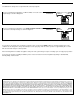
The output or motor switching side of the #950-0014 has three terminals. L1 or
the 120 VAC supply power lead is attached to terminal 2. White or the 120 VAC
neutral/return lead is attached to terminal 3 and the Black or 120 VAC “hot” motor
lead is attached to terminal 1. IMPORTANT: Terminals 2 (L1) and 3 (L2) must be
powered continuously with 120 VAC.
ELECTRICAL RATING
The Terminal 1 (Motor Load) and Terminal 3 (L2) 120 VAC Load contacts are
rated for 1/4 H.P. @ 120 VAC.
REPLACEMENT OF DEFECTIVE RELAY/TIMER
1. Remove the electrical box cover of the Power Venter.
2. Mark the Black wire on defective Timer which is the load wire to the motor. This terminal will be marked BLK MOTOR, LOAD or be
the #1 Terminal if replacing an Airotronics Timer. Remove the defective Timer and (4) plastic stand offs if necessary.
3. Place the 120 VAC supply L1 Black wire on Terminal 2. Place the White L2 wire on Terminal 3 and place the Black Motor Load wire
on Terminal 1, (See Diagram A).
NOTE: When the 120 VAC Supply power is first established to the Relay/Timer, it may automatically reset into post purge. After the
venter operates for approximately 45 seconds it will shut off and be ready for normal operation.
TJERNLUND PRODUCTS, INC.
1601 Ninth Street • White Bear Lake, MN 55110-6794
PHONE (800) 255-4208 • (651) 426-2993 • FAX (651) 426-9547
Visit our web site • www.tjernlund.com
1
3
2
5
4
MOTOR (BLACK)
L1 (BLACK)
(WHITE)
L2
LOAD
DIAGRAM 1 TIMER/RELAY OUTPUT
50/60 HZ
120 VAC
DIAGRAM A
1/4 H.P. @ 120 VAC