
Owner manual


P/N: 8505009 ©2000 TJERNLUND PRODUCTS, INC. ALL RIGHTS RESERVED REV. 08/00
TJERNLUND PRODUCTS, INC.
1601 Ninth Street • White Bear Lake, MN 55110-6794
PHONE (800) 255-4208 • (651) 426-2993 • FAX (651) 426-9547
Visit our web site • www.tjernlund.com
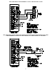
Optional Limit (Spill Switch)
Used in conjunction with Optional Alarm
Sequencer
115 VAC Proven “HOT” From Fan Prover
115 VAC Neutral To Inducer / Venter / IN-FORCER
115 VAC “HOT” To Inducer / Venter
/ IN-FORCER motor & Fan Prover
Auxiliary Operation Switch
(i.e. Manual or Gas Pressure)
115 VAC Input From Disconnect Switch
Aux. Motor in parallel with H & N used for
additional Power Venter, Inducer, IN-FORCER
Aux. Prover contacts in series with H & PH
contacts on output terminals
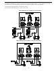
Appliance # 2
Interlock
Appliance # 1
Interlock
Appliance # 3
Interlock
Aux. Limit switch in series with
optional limit on terminal strip
Optional Alarm Sequencer proves Fan
Prover Operation (not limit operation)
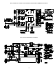
MAC-3 CIRCUIT BOARD FEATURES
P/N 950-0484 MAC-3 CIRCUIT BOARD REPLACEMENT KIT INSTRUCTIONS
FOR REPLACEMENT ON IN-FORCER MODELS PAI-3,4 WITH CIRCUIT BOARD BUILT IN
Disconnect power supply before making wiring connections to prevent electrical shock and equipment damage.
1. Jumper wire provided must be installed on optional limit location if it is not being utilized.
2. Blue and Yellow wires from Fan Prover must be connected to Auxiliary Prover (3 & 4) contacts.
3. Red wires from High Limit must be connected to Auxiliary Limit (9 & 0) contacts.
4. Gray wires from Alarm Sequencer must be connected to Alarm Sequencer (5 & 6) contacts.
Black and White wires from Alarm Sequencer must be connected to Alarm Sequencer (7 & 8) contacts.
IMPORTANT: Jumper wire must be installed across H & PH terminals when IN-FORCER Fan Prover is wired into Auxiliary Prover (3 & 4)
contacts. It is not necessary to wire the Fan Prover in series with the H & PH terminals as shown in the MAC-3 Instructions enclosed when the
Prover is wired in series with the Auxiliary Prover (3 & 4) contacts. All Fan Provers must be wired in series with the H & PH or Auxiliary Prover
(3 & 4) contacts. Do not put jumper wire across H & PH terminals if Prover circuit is installed across those terminals.
FOR REPLACEMENT ON MAC-3 CONTROLLER
Disconnect power supply before making wiring connections to prevent electrical shock and equipment damage.
1. Jumper wire provided must be installed on optional limit location if it is not being utilized.
2. Jumper wires provided must be installed on Auxiliary Prover terminals (3 & 4) and Auxiliary Limit terminals (9 & 0)
if they are not being utilized.
3. For detailed wiring see MAC-3 Instructions enclosed P/N 8504043.