
Install Instructions


TJERNLUND PRODUCTS, INC.
1601 Ninth Street • White Bear Lake, MN 55110-6794
PHONE (800) 255-4208 • (651) 426-2993 • FAX (651) 426-9547
Visit our web site • www.tjernlund.com
READ OWNERS INSTRUCTIONS CARE-
FULLY PRIOR TO INSTALLATION.
THESE INSTRUCTIONS MUST REMAIN
WITH EQUIPMENT. DO NOT DESTROY.
AIRESHARE
TM
LEVEL TO LEVEL VENTILATOR
MODEL ASLL
©2009 TJERNLUND PRODUCTS, INC. ALL RIGHTS RESERVED P/N: 8504156
DESCRIPTION
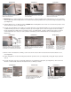
The AireShare™ Level to Level Ventilators distribute air from one conditioned space to another. Virtually every home has temperature
differentials on different levels of the house. The AireShare™ moves air from one level of the house to a room on another level of the
house that is uncomfortably hot or cold. This air movement helps to destratify stagnant air in homes, improve ventilation rates and make
both rooms more comfortable.
ASLL SPECIFICATIONS & COMPONENTS
GENERAL INFORMATION
Every Tjernlund AireShare™ Level to Level Ventilator is electrically factory line tested before shipment.
After opening carton, inspect thoroughly for shipping damage. Impeller should rotate freely and all electrical wires and connections
should be secured. If any damage is found, notify freight carrier and your distributor immediately and file a concealed damage claim.
INSTALLATION RESTRICTIONS
The AireShare™ Ventilator must be installed by a qualified installer in accordance with these instructions and all local codes or in their
absence in accordance with the latest editions of the International Residential Code and International Electrical Code. Improper installa-
tion can create a hazardous condition such as fire, electric shock or personal injury. To reduce these risks significantly, use this device
only in the manner intended by the manufacturer. If you have questions about proper usage of this device, call Tjernlund Products.
Always disconnect the AireShare™ Ventilator from its power source before installation and servicing.
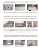
IMPORTANT: An in depth investigation of the floor joist/truss layout is required prior to installation. Avoid a floor/ceiling cavity that is a
path for plumbing supply lines, drains, vents or ductwork. Also confirm foundation block and upstairs walls do not obstruct installation.
SPECIFICATIONS
Blower: 75 cfm
Motor: 115 Volts ~ 60 Hz
25 Watts ~ 0.50 amps maximum
Impeller: Transtangental, cross-flow
Sound: 42 db (1.15 Sones)
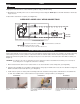
DIMENSIONS:
White Ceiling Grille: 5 1/2” x 13 1/2” (flush)
Brown Floor Grille: 5 3/4” x 13 3/4” (flush)
Blower Housing Rough-in: 4 1/16” x 12 5/16”
Outer Sleeve Rough-In: 4 5/16” x 12 5/16”
Expansion Depth* 8 3/4” to 16 1/2”
(*top of floor to bottom of ceiling)
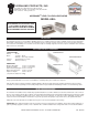
CEILING GRILLE
FLOOR GRILLE
EXPANSION DEPTH