
Install Instructions


3. Place ASLL Outer Sleeve template center alignment hole over drill bit or screw driver. Align template cutout lines parallel with
baseboard and tape template to floor, (See Diagram C). Use a utility knife and cut out carpeting and pad along Outer Sleeve
template lines denoted, (See Diagram D).
4. Drill the 4 corners out on floor with a 3/8” drill bit and saw opening out using a jig saw or reciprocating saw. The final rough-in opening in
the floor for an Upflow application must measure 4 5/16” x 12 5/16” for Outer Sleeve. IMPORTANT: Rough-in openings must
not exceed dimensions provided or Outer Sleeve flange may fall through opening, (See Diagram E).
5. Proceed to step 8 if ceiling below is unfinished. Slide the Outer Sleeve through the floor. Using a 1/4” long drill bit, follow the corners of
the Outer Sleeve straight down and drill 4 holes through the ceiling material below, (See Diagram F). Connect the 4 holes on the ceiling
below with a straight edge and compare the dimensions on the ceiling to Blower Housing template dimensions which measure 4 1/16” x
12 5/16”, See Diagram G).
6. If ceiling is sheetrock use a sheetrock saw and follow the lines from step 5 and cut out ceiling opening, (See Diagram G). If ceiling is
not sheetrock, use a jig saw or reciprocating saw. IMPORTANT: Both openings should be directly centered above one another.
7. If ceiling is sheetrock or ceiling tile, slide sheetrock mounting brackets over sheet rock ends. The 2 large holes in brackets must face
down, (See Diagram H). IMPORTANT: If using ceiling tile, it must be able to support 8 pounds to support the ASLL blower. If ceiling
tile is not adequate enough to support the ASLL then the ASLL must be framed in and properly supported by ceiling track.
8. Use a rod with wire attached to ASLL Blower Housing mounting bracket to suspend ASLL blower from floor above while
wiring, (See Diagram I).
9. Supply electrical power through ceiling opening on the side of ASLL where power will enter unit. See “Wiring” section for wiring
specifics. Use provided strain relief bushing for standard 14-2 w/ground NM-B nonmetallic sheathed cable (Romex) and snap into
place in 7/8” knockout on ASLL electrical box with about 6-8” of wire pushed into ASLL electrical box, (See Diagram J). Push wire up
tight against ASLL Blower Housing and slide the ASLL up through the hole in the ceiling until the flange of the ASLL blower section
meets the ceiling, (See Diagram K).
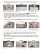
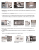
DIAGRAM B DIAGRAM C DIAGRAM D
IF CEILING IS FINISHED, PLACE TAPE ALONG
JOIST/TRUSS. CUT A 3” INSPECTION HOLE TO
VERIFY IT IS A GOOD INSTALLATION LOCATION.
PLACE ASLL OUTER SLEEVE TEMPLATE CEN-
TER ALIGNMENT HOLE OVER DRILL BIT OR
SCREW DRIVER.
FOR AN UPFLOW APPLICATION CUT OUT CAR-
PET & ROUGH-IN OPENING USING OUTER
SLEEVE TEMPLATE (4 5/16” X 12 5/16”).
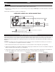
DIAGRAM E
DRILL OUT CORNERS WITH 3/8” DRILL BIT.
IMPORTANT: ROUGH-IN OPENING FOR OUTER
SLEEVE MUST NOT EXCEED 4 5/16” X 12 5/16”.
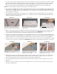
DIAGRAM F DIAGRAM G
CONNECT (4) HOLES WITH A STRAIGHT EDGE
AND MAKE SURE BLOWER HOUSING DIMEN-
SIONS MEASURE 4 1/16” X 12 5/16”. CUT OUT
OPENING WITH SHEETROCK OR JIG SAW.
DIAGRAM I
SUPPORT ASLL BLOWER FROM ABOVE BY
USING ASLL MOUNTING FLANGE AND MECHAN-
ICS WIRE OR OTHER SUITABLE METHOD.
SNAP PROVIDED STRAIN RELIEF BUSHING INTO
ASLL ELECTRICAL BOX WITH 6-8” OF WIRE IN
ELECTRICAL BOX.
DIAGRAM J
IF CEILING BELOW IS FINISHED, DRILL (4) 1/4”
HOLES THROUGH CEILING USING EACH OF
THE 4 CORNERS OF OUTER SLEEVE AS A
GUIDE.
DIAGRAM H
INSTALL SHEETROCK BRACKETS ON BOTH
ENDS OF OPENING WITH LARGER HOLES IN
BRACKETS FACING DOWN.