
Install Instructions

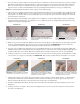
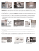

10. Using the (4) provided black screws, align holes on ASLL Blower Housing mounting bracket with holes in sheetrock mounting brack-
et (utilized if ceiling is sheetrock or ceiling tile). Install the (4) screws straight up. The screws must grip the sheetrock mounting
bracket small grip hole. Do not over tighten screws, (See Diagram L). If ceiling is unfinished cut (2) pieces from floor cutout
material and secure each piece to the joist/truss and install (4) screws in ASLL Blower Housing mounting bracket, (See Diagram L).
11. Wire the ASLL as illustrated in the “Wiring” section. Push the wires into the ASLL electrical box and install electrical box cover
and ceiling grille with the provided screws, (See Diagram M). Ceiling grille may be painted if desired.
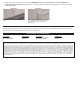
12. IMPORTANT: If the combined width of the Joist/Truss thickness, ceiling and subfloor is over 13”, adhere both air flow leakage stickers
over electrical relief slot opening in Outer Sleeve to prevent air leakage into joist/truss cavity, (See Diagram N).
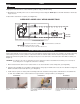
13. Install the Outer Sleeve in floor. CAUTION: When installing Outer Sleeve make sure electrical relief opening is on the side electrical
enters ASLL, (See Diagram O).
14. Unit can be operated by switching the on/off switch below floor grille, (See Diagram P). ASLL can also be wired into a 120 VAC wall
switch or thermostat if desired, see “Wiring” for details. Insert the floor grille.
IMPORTANT: An in depth investigation of the floor joist/truss layout is required prior to installation. Avoid a joist/truss cavity that is a
path for plumbing supply lines, drains, vents or ductwork. Also confirm foundation block and upstairs walls do not obstruct installation. If
wiring to an existing outlet, it is best to select a joist/truss section that contains an electrical outlet for wiring.
DIAGRAM P
ASLL CAN BE OPERATED BY ON/OFF
SWITCH THROUGH FLOOR GRILLE OR IT
CAN BE WIRED INTO A 120 VAC WALL
SWITCH OR THERMOSTAT.
IMPORTANT: IF ASLL OUTER SLEEVE WILL BE
EXPANDED OVER 13”, AIR FLOW LEAKAGE
STICKERS MUST BE APPLIED OVER ELECTRI-
CAL RELIEF SLOT TO PREVENT AIR LEAKAGE.
DIAGRAM N
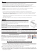
The following steps must be completed to convert the ASLL from an upflow to a downflow installation.
Remove (1) screw from On/Off switch coverplate. Pull On/Off cover assembly out and remove Blue & Red wires connected to
switch. Turn ASLL over and remove electrical access coverplate from opposite side. Pull Blue & Red wires through and
connect to On/Off switch terminals - Red to center, Blue to other, (See Diagram A1). Reinstall On/Off assembly with (1) screw,
(See Diagram A2). Reinstall electrical access coverplate on opposite side.
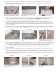
Remove (3) screws from blower guard screen, turn ASLL over and and reinstall blower guard screen flush against both outer
edges of ASLL blower housing to prevent contact with moving blower wheel, (See Diagram A3).
FEED ON/OFF SWITCH WIRES THROUGH FROM
OTHER SIDE AND PUSH ON MALE SWITCH TER-
MINALS - RED TO CENTER, BLUE TO OTHER.
INSTALL ON/OFF ASSEMBLY WITH (1) SCREW
REMOVED FROM OTHER SIDE. REINSTALL
ELECTRICAL ACCESS COVERPLATE ON OPPO-
SITE SIDE.
DIAGRAM A1 DIAGRAM A2
INSTALL BLOWER GUARD SCREEN WITH (3)
SCREWS REMOVED FROM OTHER SIDE.
DIAGRAM A3
DIAGRAM O
INSTALL OUTER SLEEVE THROUGH FLOOR.
CAUTION: ELECTRICAL RELIEF SLOT MUST BE
ON SIDE ELECTRICAL ENTERS ASLL OR DAM-
AGE MAY RESULT.
OUTER SLEEVE
ELECTRICAL RELIEF SLOT
THE FOLLOWING STEPS ARE FOR A DOWNFLOW INSTALLATION
APPLY
STICKERS
OVER
RELIEF
SLOT IF
EXPAND
OVER 13”
RELIEF
SLOT
DIAGRAM L
INSTALL (4) SCREWS
IN BLOWER HOUSING
MOUNTING FLANGE
INTO SHEETROCK
MOUNTING BRACKET.
FOR UNFINISHED CEIL-
INGS, SCREW PIECES
OF WOOD CUT FROM
FLOOR OPENING TO
JOIST/TRUSS TO SUP-
PORT ASLL BLOWER.
INSTALL CEILING GRILLE
INTO SHEETROCK
MOUNTING BRACKET
WITH PROVIDED SCREWS.
DIAGRAM M
WIRE PER WIRING
DIAGRAM. INSTALL
ASLL ELECTRICAL
BOX COVER.
DIAGRAM K
PUSH WIRE UP TIGHT AGAINST ASLL BLOWER
HOUSING AND SLIDE UP UNTIL FLUSH WITH
CEILING.