REV. 08/02 TJERNLUND PRODUCTS, INC. 1601 Ninth Street • White Bear Lake, MN 55110-6794 PHONE (800) 255-4208 • (651) 426-2993 • FAX (651) 426-9547 Visit our web site • www.tjernlund.com VERSION X.02 OR EARLIER FOR NATURAL GAS, LP OR OIL INCLUDES NEW UC1 UNIVERSAL CONTROL MODELS HSJ HS1 HS2 OWNER INSTRUCTIONS, DO NOT DESTROY ! Recognize this symbol as an indication of important Safety Information! NOTE: FLUE GAS TEMPERATURES MUST NOT EXCEED 600OF AT VENT SYSTEM INLET FOR U.S.
Address all correspondence to: Customer Service • Tjernlund Products, Inc. • 1601 Ninth Street • White Bear Lake, MN 55110-6794 Call us toll free at 800-255-4208, visit our web site @ www.tjernlund.com or email us at fanmail@tjfans.com. TABLE OF CONTENTS PAGE(S) SIZING TABLES AND SPECIFICATIONS ..................................................................................................................................... 1 - 2 INSTALLATION RESTRICTIONS ..................................................
UC1 UNIVERSAL CONTROL SPECIFICATIONS POWER REQUIREMENTS T-BLOCK L/N XL / XN ADD VENTER MOTOR LOAD PLUS 1/2 AMP FOR UC1 LOAD EXTERNAL POWER SWITCHING CAPACITY UC1 CONTROL 150 mA MAX @ 120 VAC, 50/60 Hz CAN ONLY BE CONNECTED TO TJERNLUND-SPECIFIED AUXILIARY DEVICE DURING OPERATION THE CONTROL USES 50 mA MAX @ 120 VAC M & MTR (RELAY K2) MOTOR - 1 H.P. MAX. @ 120 VAC, 50/60 Hz GENERAL PURPOSE - 15A @ 120 VAC, 50/60 Hz T-BLOCK 3 TO 4 (RELAY K1) MOTOR - 1 H.P. MAX.
Failure to install, maintain and/or operate the Power Venter in accordance with manufacturer's instructions may result in conditions which can produce bodily injury and property damage. Disconnect power supply from the UC1 and heating equipment when making wiring connections and servicing the Venter. Failure to do so may result in personal injury and/or equipment damage. LED #5 (RED) should be off with power removed. 1.
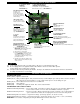
UC1 UNIVERSAL CONTROL BOARD FEATURES P1 - P2 SAFETY CIRCUIT TERMINALS 1 mA @ 5VDC. SEE WARNING # 1. DIP SWITCH SETTINGS Pre-Purge (1-2) Post-Purge (3-8) Prover status check (9) See “Pre / Post Purge & Prover Status Check Dip Switch Settings”. C, GND, F AUXILIARY DEVICE COMMUNICATION TERMINALS 2 mA @ 5VDC. For Tjernlund MAC1E or MAC4E auxiliary devices. SEE WARNING # 1. P1 P2 LED STATUS LIGHTS See “LED Status & Fault Indicator Section” for details.
PRE / POST PURGE AND PROVER STATUS CHECK DIP SWITCH SETTINGS Remove power to UC1 and heating equipment when installing, servicing or changing dip switch settings. Failure to do so may result in personal injury and/or equipment damage. LED #5 (RED) should not be on if 115 VAC supply power is removed from the control. Pre-purge Used for a Venter with longer vent runs to get draft fully established throughout the vent system prior to burner ignition. Also beneficial for negative pressure prone environments.
INSTALLATION VENT SYSTEM TERMINATION Before installing Power Venter determine location of vent system termination. TOOLS REQUIRED • Saber Saw or Cement Drill • Wood or Masonry Chisel • Drill • Blade Screwdriver or 1/4” Nut Driver • 1/8” and 1/4” Drill Bits • Wire Cutter/Stripper For oil installations do not terminate HS-Series Power Venters on vinyl siding because temperatures can easily exceed 150 0F.
VENT HOOD TERMINATION CODE REQUIREMENTS FOR CANADIAN INSTALLATIONS If possible, locate the Vent Hood on a wall that does not face the direction of prevailing winds. This will diminish the possibility of appliance interruption during periods of extreme winds and prevent oil odors caused by backdrafts. N TER • A venting system shall not terminate underneath a veranda, porch, or deck, or above a paved sidewalk or a paved driveway that is located between two buildings, and that serves both buildings.
INSTALLATION RESTRICTIONS DIAGRAM A 1. Power Venter must be installed as close as possible to the termination of the vent system to obtain optimal appliance efficiency and to prevent flue gas leakage, (See Diagram A). 2. The Power Venter may be mounted in any position as long as the shaft of the motor remains horizontal, to prevent motor bearing wear and to ensure proper Fan Proving Switch operation, (See Diagram B). DIAGRAM B DIAGRAM C 3. The Power Venter housing is single wall. A 6” (15.
POWER VENTER MOUNTING 1. Slide the outlet of the Power Venter over the inner sleeve of the Vent Hood and connect them together using a tapered transition fitting if necessary, (See Diagram G). If you are unable to make a direct connection to the Vent Hood, vent pipe may be installed between the Power Venter and Vent Hood. However, all vent pipe connections after the Power Venter must be sealed with high temperature silicone caulk or aluminum vent pipe tape to prevent flue gas leakage, (See Diagram E). 2.
(UPFLOW APPLIANCE) UC1 UNIVERSAL CONTROL INSTALLATION AND MOUNTING The UC1 has a 2 foot whip that contains a ground lead and the leads to power the Venter motor and connect to the Fan Prover. If it is desirable to mount the UC1 more than 2 feet from the Venter an additional electrical junction box and appropriate length of conduit will be necessary. Any added wire should be 14 gauge and a pig tail should be added to each ground wire connection so that each electrical junction box is grounded.
UC1 UNIVERSAL CONTROL WIRING SCHEMATIC The Ground lead, Venter motor and Fan Prover leads are factory connected to the UC1 circuit board. Venter Ground, motor and Fan Prover wiring connections are made at the free end of the 2 foot whip in HS-Series junction box.
UC1 UNIVERSAL CONTROL CONNECTED WITH A 24 VAC ELECTRONIC IGNITION MODULE IMPORTANT: RED JUMPER POSITION MUST BE THE SAME AS APPLIANCE INTERLOCK VOLTAGE. OR 24V (8) CALL JUMPER J1 BNR GND (4) PV (3) MV / PV (2) MV (1) YE SUPPLY 115 VAC 50/60 Hz GR YE XN (5) XL 24V GND PI R (6) UNIVERSAL CONTROLLER J2 (7) 24V DRY (9) 115V SPARK YE GROUND PV WH OR WH OR HONEYWELL IGNITION CONTROL PV MV IMPORTANT: CRIMP GROUND WIRE TO GROUNDING SPADE TERMINAL IN ELECTRICAL BOX.
UC1 UNIVERSAL CONTROL CONNECTED WITH A SINGLE ZONE 24 VAC THERMOSTAT IMPORTANT: RED JUMPER POSITION MUST BE THE SAME AS APPLIANCE INTERLOCK VOLTAGE. G W CALL JUMPER G C J1 Y W XL SUPPLY 115 VAC 50/60 Hz XN R GROUND UNIVERSAL CONTROLLER J2 R INTERNAL CONTROL OF FURNACE 24V Y R DRY 115V THERMOSTAT LEGEND: 115 VAC 24 VAC IMPORTANT: CRIMP GROUND WIRE TO GROUNDING SPADE TERMINAL IN ELECTRICAL BOX. D/N 9183046-5 1. 2. 3. 4. 5. Connect W from t-stat to #1 on terminal block of UC1.
UC1 UNIVERSAL CONTROL CONNECTED TO A GAS OR OIL BURNER WITH AN AQUASTAT IMPORTANT: RED JUMPER POSITION MUST BE THE SAME AS APPLIANCE INTERLOCK VOLTAGE. AQUASTAT C2 D/N 9183046-7 B1 24V L2 115 VAC DRY C1 115V L1 LEGEND: CALL JUMPER B2 J1 L1 XL SUPPLY 115 VAC 50/60 Hz GROUND XN R LINE VOLTAGE OIL BURNER PRIMARY CONTROL, BURNER RELAY OR GAS VALVE UNIVERSAL CONTROLLER J2 N IMPORTANT: CRIMP GROUND WIRE TO GROUNDING SPADE TERMINAL IN ELECTRICAL BOX.
UC1 UNIVERSAL CONTROL CONNECTED WITH A CARLIN 40200, 42230, 48245, 50200, 60200 SERIES OR EQUIVALENT AND A LINE VOLTAGE THERMOSTAT OR AQUASTAT SUPPLY 115 VAC 60 Hz T Red/White Low Voltage Jumper T Black Orange 10 FLA / 60 LRA BURNER MOTOR A Blue 500 VA CALL JUMPER IGNITION TRANS 0.3 A, AC OIL VALVE J1 XL SUPPLY 115 VAC 50/60 Hz XN R GROUND UNIVERSAL CONTROLLER Violet J2 Alarm A 24V F IMPORTANT: RED JUMPER POSITION MUST BE THE SAME AS APPLIANCE INTERLOCK VOLTAGE.
UC1 UNIVERSAL CONTROL CONNECTED WITH A HONEYWELL R8184 SERIES OR EQUIVALENT PRIMARY CONTROL AND A BURNER MOTOR POST-PURGE L1 THERMOSTAT BLACK ORANGE WHITE B T O T W F IMPORTANT: RED JUMPER POSITION MUST BE THE SAME AS APPLIANCE INTERLOCK VOLTAGE.
DRAFT CHECK, SAFETY INTERLOCK & COMBUSTION AIR TEST The Power Venter Fan Proving Switch is designed to disable the appliance gas valve or burner motor upon Power Venter failure only! It is not designed and cannot replace, regular vent system inspection, appliance servicing and combustion testing. DIAGRAM I 1. Close all doors and windows of the building. If the appliance is installed in a utility room or closet, close the entrance door to this room. Close fireplace dampers. 2.
MAINTENANCE 1. The HSJ,1,2 motors are permanently lubricated and do not need to be oiled. 2. The end-user must semiannually inspect the Vent Hood and vent pipe for blockage, corrosion and leaks. 3. A vent system inspection must be performed annually by a qualified service agency. The inspection should include the operation circuit check, safety interlock test, combustion air test and a visual inspection of the complete vent system for corrosion, blockage or leaks.
Verify that LED #2 (Green) is lit. Yes, LED #2 (Green) is lit: Verify that "call jumper" is connected from J1 to J2 on UC1 circuit board. With call for heat established, verify that wiring is correct by measuring voltage between terminals 1 & 2 and 2 & 4 of UC1 terminal strip. Voltage should be the same in both cases, if not rewire per appropriate diagram. NOTE: If using the “Dry Contact” interlock method, make sure that the RED voltage selection jumper is installed on the dry contact tabs.