
Install Instructions


13
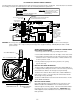
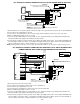
UC1 UNIVERSAL CONTROL CONNECTED WITH A SINGLE ZONE 24 VAC THERMOSTAT
XN
R
UNIVERSAL CONTROLLER
THERMOSTAT
GG
INTERNAL CONTROL
OF FURNACE
W
C
Y
R
R
Y
AS APPLIANCE INTERLOCK VOLTAGE.
RED JUMPER POSITION MUST BE THE SAME
XL
J1J2
W
DRY
115V
24V
IMPORTANT:
D/N 9183046-5
115 VAC
24 VAC
LEGEND:
CALL
JUMPER
50/60 Hz
SUPPLY
115 VAC
SPADE TERMINAL IN ELECTRICAL BOX.
GROUND
CRIMP GROUND WIRE TO GROUNDING
IMPORTANT:
1. Connect W from t-stat to #1 on terminal block of UC1.
2. Connect #2 on UC1 terminal block to C on internal control terminal strip of furnace/boiler.
3. Connect #4 on UC1 terminal block to W on internal control terminal strip of furnace/boiler.
4. Make sure RED voltage jumper on UC1 is on 24V.
5. Connect 115 VAC supply voltage to L & N terminals on UC1. Crimp Ground wire to grounding spade terminal in UC1.
Important: Installer must supply overload and disconnect protection.
6. If not previously completed, connect ground from UC1 whip to grounding stud in Venter. Connect Black and White leads
from UC1 whip to Venter motor leads. Connect Blue and Yellow leads from UC1 whip to Fan Prover switch terminals in
Venter. Yellow lead should be on switch terminal closest to Venter junction box wall.
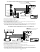
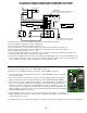
UC1 UNIVERSAL CONTROL AND WHKE INTERLOCK KIT
CONNECTED WITH A MILLIVOLT APPLIANCE
XN
R
UNIVERSAL CONTROLLER
D/N 9183046-9
CALL
AS APPLIANCE INTERLOCK VOLTAGE.
RED JUMPER POSITION MUST BE THE SAME
XL
J1J2
DRY
115V
24V
IMPORTANT:
JUMPER
GENERATED
5 VDC
LEGEND:
115 VAC
WHKE GAS
SAFETY CIRCUIT ACROSS P1 & P2 OF UC1 IS NOT UTILIZED
WITH HEATING EQUIPMENT AS SHOWN.
IN THIS APPLICATION. SPILL SWITCH MUST BE INTERLOCKED
MILLIVOLT
PRESSURE
SWITCH
JUNCTION ADAPTER
THERMOCOUPLE
950-0470 (JA1)
LINEAR LIMIT
SPILL SWITCH
GAS
VALVE
30 MILLIVOLT WATER HEATERS REQUIRE USE OF THE
(ECO) OF WATER HEATER. LINEAR LIMIT SPILL SWITCH,
ON 750 MILLIVOLT (POWER PILE) WATER HEATERS WIRE
LINEAR LIMIT SPILL SWITCH IN SERIES WITH HIGH LIMIT
950-0470 THERMOCOUPLE JUNCTION ADAPTER.
950-0470 JUNCTION ADAPTER AND GAS PRESSURE
SWITCH ARE INCLUDED WITH WHKE KIT.
DO NOT
SUPPLY
POWER.
POWER!
BOARD-
50/60 Hz
SUPPLY
115 VAC
ELECTRICAL BOX.
GROUND
CRIMP GROUND WIRE TO GROUNDING SPADE TERMINAL IN
IMPORTANT:
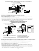
Each millivolt appliance interlocked with the UC1 must have its own WHKE kit installed. The WHKE Gas Pressure Switch actuates the
Venter through the A - B Dry contacts. The Linear Limit switch disables the heater in the event of a venting malfunction. IMPORTANT:
Each millivolt appliance interlocked with the UC1 must have its own Linear Limit spill switch.
1. Wire WHKE Gas Pressure Switch across A and B terminals on UC1. Do not supply voltage to A and B terminals.
2. Wire WHKE Linear Limit in series with thermocouple junction adapter or high limit ECO of water heater.
3. Make sure RED voltage jumper on UC1 is in the DRY position.
4. Connect 115 VAC supply voltage to L & N terminals on UC1. Crimp Ground wire to grounding spade terminal in UC1.
Important: Installer must supply overload and disconnect protection.
5. If not previously completed, connect ground from UC1 whip to grounding stud in Venter. Connect Black and White leads
from UC1 whip to Venter motor leads. Connect Blue and Yellow leads from UC1 whip to Fan Prover switch terminals in
Venter. Yellow lead should be on switch terminal closest to Venter junction box wall.