
Install Instructions


16
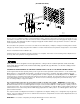
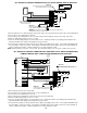
UC1 UNIVERSAL CONTROL CONNECTED WITH A HONEYWELL R8184 SERIES
OR EQUIVALENT PRIMARY CONTROL AND A BURNER MOTOR POST-PURGE
RED JUMPER POSITION MUST BE THE SAME
AS APPLIANCE INTERLOCK VOLTAGE.
UNIVERSAL CONTROL
XN
BURNER
N MTRM
THERMOSTAT
OIL VALVE
W
O
WHITE
ORANGE
B
F
F
T
T
IMPORTANT:
XL
J1J2
115V
DRY
24V
D/N 9183047-4
115 VAC
LEGEND:
CALL
JUMPER
BLACK
HONEYWELL R8184
SERIES OR EQUIVALENT
L1
VENTER
MOTORMOTOR
IGNITION
TRANS
50/60 Hz
SUPPLY
115 VAC
SPADE TERMINAL IN ELECTRICAL BOX.
GROUND
CRIMP GROUND WIRE TO GROUNDING
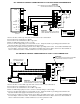
IMPORTANT:
1. Separate the burner motor wire and ignition transformer from the Orange wire of R8184.
2. Connect the Orange of R8184 to #1 on UC1 terminal block.
3. Connect #2 on UC1 terminal block to White on R8184 or N.
4. Connect the HOT wire of oil solenoid valve to #4 on UC1 terminal block and neutral wire to White or N.
5. Connect burner motor and ignition transformer HOT wires to M terminal on UC1 and neutrals to White or N.
6. Make sure RED voltage jumper on UC1 is on 115V.
7. Connect 115 VAC supply voltage to L & N terminals on UC1. Crimp Ground wire to grounding spade terminal in UC1.
Important: Installer must supply overload and disconnect protection.
8. If not previously completed, connect ground from UC1 whip to grounding stud in Venter. Connect Black and White leads
from UC1 whip to Venter motor leads. Connect Blue and Yellow leads from UC1 whip to Fan Prover switch terminals in
Venter. Yellow lead should be on switch terminal closest to Venter junction box wall.
UC1 UNIVERSAL CONTROL OPERATIONAL CHECK
1. Confirm power is supplied to the Control. LED #5 (RED) should be on.
2. Activate the UC1 by initiating an appliance call for heat. LED #1 (AMBER) should be on.
3. The motor relay will close and activate the Venter motor. LED #3 (GREEN) should be on and Venter
motor should be running.
4. If the safety circuit across P1 & P2 (Venter Prover) is closed, indicating an approved condition, the
appliance interlock relay will close making terminal #3 closed to terminal #4 & LED #2 (GREEN).
5. Remove power to the UC1 and any interlocked appliances. The LED #5 (RED) or any LED’s should
not be on. Test the safety circuit by removing the Blue or Yellow lead from Fan Proving switch in
HS-Series electrical box. Do not let the opened LEAD touch a ground or damage may occur to the
control when power is Reestablished. Reestablish power to the UC1 and interlocked appliances and
initiate an appliance call for heat. After 60 seconds a Prover Start Up fault should arise with LED #4
(RED) and LED #5 (RED) flashing in unison.
6. Remove appliance call for heat and power to the UC1 and any interlocked appliances. The LED #5
(RED) or any LED’s should not be on. Reconnect Blue or Yellow Fan Prover lead to Fan Prover Switch
terminal removed from in step 5.
7. Reestablish power to UC1 and interlocked appliances and initiate a call for heat to confirm proper operation of UC1 and appliance.
ON