
Install Instructions


INSTALLATION RESTRICTIONS
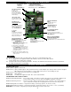
1. Power Venter must be installed as close as possible to the termination of the vent system to obtain
optimal appliance efficiency and to prevent flue gas leakage, (See Diagram A).
2. The Power Venter may be mounted in any position as long as the shaft of the motor remains
horizontal, to prevent motor bearing wear and to ensure proper Fan Proving Switch operation,
(See Diagram B).
3. The Power Venter housing is single wall. A 6” (15.2 CM) clearance
to combustibles must be maintained for gas and 18” (45.7 CM) clear-
ance for oil applications, (See Diagram C). If the appliance name
plate specifies a vent connector clearance greater than 6 inches, the
greater clearance must be used. Verify these clearances are in
compliance with all local codes.
NOTE: Clearance to combustibles may be reduced. Please refer to
Clearance Table VI in NFPA #54 or your local code authority.
4. Vent pipe transitions, where necessary, must be gradually tapered,
(See Diagram D).
5. Power Venter to vent pipe connections and all joints on the outlet side of the Power Venter must be sealed with high-temperature silicone
sealant or aluminum vent pipe tape to prevent flue gas leakage, (See Diagram E).
6. Oil installations require the use of a barometric draft control. Draft control must be installed between the appliance outlet and the Power
Venter inlet, (See Diagram E). Oil installations should use the same diameter pipe on the inlet and discharge side of the Power Venter.
7. Allow for a minimum straight section of pipe equal to 3 times the diameter of the vent pipe being used when installing elbows on the
discharge side of the Power Venter. For example, if using 4” pipe, allow for 12” of straight pipe before using an elbow, (See Diagram F).
8
DIAGRAM A
DIAGRAM B
DIAGRAM D
DIAGRAM E
ELBOW
PIPE
BEFORE ELBOW
SECTION OF PIPE
ADD A STRAIGHT
VENT PIPE
DIAMETER
3 TIMES
2201018D
DIAGRAM F
DIAGRAM C