
DJ3_D3_I_IL_XL Installation Manual


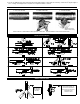


TABLE OF CONTENTS
PAGE(S)
DESCRIPTION............................................................................................................................................................... 1
SPECIFICATIONS.......................................................................................................................................................... 1
CAUTIONS..................................................................................................................................................................... 1
INSTALLATION RESTRICTIONS................................................................................................................................... 2
DRAFT INDUCER SELECTION TABLE ........................................................................................................................ 2
PS1505 FAN PROVER SAFETY INTERLOCK INSTALLATION ................................................................................... 3
INSTALLATION ......................................................................................................................................................... 3 - 5
ELECTRICAL WIRING .............................................................................................................................................5 - 9
TYPICAL GAS DIAGRAMS........................................................................................................................ 5 - 8
TYPICAL OIL DIAGRAMS.......................................................................................................................... 8 - 9
OPERATION CIRCUIT CHECK.............................................................................................................................. 9 - 10
P/N 950-1067 POST PURGE RELAY/TIMER ADJUSTMENT ................................................................................... 10
COMBUSTION AIR & SAFETY INTERLOCK TEST.....................................................................................................10
DRAFT CONTROL........................................................................................................................................................10
MAINTENANCE .................................................................................................................................................... 10 -11
HOW TO OBTAIN SERVICE & LIMITED WARRANTY................................................................................................ 11
REPLACEMENT PARTS.............................................................................................................................................. 11
Tjernlund Products welcomes your comments and questions. Call us at (651) 426-2993, (800) 255-4208, Fax (651) 426-9547, email us
at fanmail@tjfans.com or write to: Customer Service, Tjernlund Products, Inc., 1601 Ninth Street, White Bear Lake, MN 55110-6794.
DESCRIPTION
TJERNLUND AUTO-DRAFT
®
Inducers assure positive draft when restricted boilers and furnaces, poor chimneys or slight negative pres-
sures in buildings prevent proper exhaust of combustion gas. The venturi action of Tjernlund Auto-Draft Inducers starts air moving
smoothly. These units are quick and easy to install and completely automatic in operation. Tjernlund’s unique design and durable con-
struction makes them trouble-free and reduces maintenance to a minimum. The Vari-Draft Control permits adjustments to the individual
job requirement.
SPECIFICATIONS
CAUTIONS
Disconnect the power supply when making wiring connections or when working around the fan wheel and motor. Failure to do so can
result in electrical shock, personal injury, death or property damage.
1. All wiring must comply with applicable codes and ordinances.
2. When wiring is completed, check all components by running system through its entire heating cycle. See “Operation Circuit Check”
on page 9 and “Safety Interlock / Combustion Air Test” on page 10.
3. Check vent pipe system for leakage. All vent system leaks must be sealed prior to the installation of the Draft Inducer.
4. Plan the vent system so that Code required distances are maintained from plumbing and wiring.
5. Make certain the power supply is adequate for the Draft Inducer motor requirements. Do not add the Draft Inducer to a circuit
where the total load is unknown. For Draft Inducer motor amperage see “Draft Inducer Selection Table” on page 2.
6. The Draft Inducer shall not be installed where flue gas temperatures exceed 575
O
F at the Draft Inducer Inlet. Ambient tempera-
tures must not exceed 104 degrees F. Item #4 under “Installation Restrictions” describes how to measure flue gas temperatures.
7. A safety inspection of an existing appliance must be performed before installation of the Draft Inducer as outlined in ANSI
Z223.1/NFPA #54, Appendix H.
1
“H” - OVERALL HEIGHT
“D” - OVERALL DEPTH
“W” - OVERALL WIDTH
“X” - PIPE SLOT WIDTH
“Y” - PIPE SLOT HEIGHT