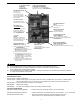
REV. C 02/04 TJERNLUND PRODUCTS, INC. 1601 Ninth Street • White Bear Lake, MN 55110-6794 PHONE (800) 255-4208 • (651) 426-2993 • FAX (651) 426-9547 Visit our web site • www.tjernlund.com VERSION X.04 INCLUDES NEW UC1 UNIVERSAL CONTROL MODEL SS1 INSTALLATION INSTRUCTIONS ! Recognize this symbol as an indication of important Safety Information! OWNER INSTRUCTIONS, DO NOT DESTROY NOTE: FLUE GAS TEMPERATURES MUST NOT EXCEED 650oF AT VENT SYSTEM INLET.
Tjernlund Products welcomes your comments and questions. Address all correspondence to: Customer Service • Tjernlund Products, Inc. • 1601 Ninth Street • White Bear Lake, MN 55110-6794 Call us toll free at 800-255-4208, visit our web site @ www.tjernlund.com or email us at fanmail@tjfans.com. TABLE OF CONTENTS Page (s) Description and Specifications ....................................................................................................................................
SPECIFICATIONS Motor: 115/1/60, 3300 RPM, 212 watts, 2.28 FLA Fan Proving Switch: Non-adjustable set point of -.05" W.C. High Limit: Manual reset, N/C contacts, open at 135oF + 10oF. UC1 Universal Control: See UC1 Universal Control Board Features on page 4. Pre-Purge: Options (0, 5, 20, 35 seconds); Post-Purge: Factory set at 2 minutes, Options (0, 30 seconds or 1, 2, 4, 8, 16 minutes). See page 5 for Pre / Post-purge options.
CAUTIONS The SS1 must be installed by a qualified installer (an individual properly licensed and/or trained) in accordance with all local codes or, in their absence, in accordance with the appropriate National Fire Protection Association #31, #54, #211 and the National Electrical Code. Failure to install, maintain and/or operate the SS1 in accordance with manufacturer's instructions may result in conditions which can produce bodily injury and property damage. 1. The installer must verify that the BTU/hr.
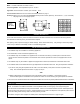
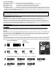
SS1 WITH INTEGRAL UC1 UNIVERSAL CONTROL BOARD FEATURES C, GND, F AUXILIARY DEVICE COMMUNICATION TERMINALS 2 mA @ 5VDC. For Tjernlund MAC1E or MAC4E auxiliary devices. SEE WARNING # 1. P1 - P2 SAFETY CIRCUIT TERMINALS 1 mA @ 5VDC. SEE WARNING # 1. DIP SWITCH SETTINGS Pre-Purge (1-2) Post-Purge (3-8) Prover status check (9) See “Pre / Post Purge & Prover Status Check Dip Switch Settings”. P1 P2 LED STATUS LIGHTS See “LED Status & Fault Indicator Section” for details.
LED FAULT INDICATORS Fault conditions are indicated by counting the number of times LED #4 (Red) flashes. LED #4 Flashes 2 Times Fan Prover was in electrically closed position prior to venter operation. LED #4 Flashes 3 Times* Fan Prover does not close within 60 seconds after call for heat. LED #4 Flashes 4 Times* Fan Prover did not re-close after 10 minutes of Venter operation. LED #4 Flashes 5 Times* Fan Prover opened for more than 10 seconds during burner cycle but closed within 10 minutes.
P1 & P2 PRE-CYCLE FAN PROVER STATUS CHECK Pre-Cycle Prover Status Check Deactivated 9 The Pre-Cycle Prover Status Check is deactivated from the factory on the SS1 Series. Because of the low set point of the SS1 Fan Prover (as low as .03" w.c.) cross winds may cause the Fan Prover to close prior to a call for heat. Activating the Prover Status Check on the SS1 may cause nuisance lockouts.
INSTALLATION Tools required: • Reciprocating Saw • Drill and 1/8", 1/4", 1/2" Bits • Blade Screwdriver • Wire Cutter/Stripper • Tube Cutter • 1/2", 7/16",5/8" Wrench • 1/4" Masonry Drill Bit • 1/4", 5/16”, 11/32" Nut Runner or Socket • Hammer INSTALLING VENT HOOD TERMINUS 1. a) Fold template A (Page 25) along dashed line and attach in between the floor joists ensuring that it is snug against the sill plate and right hand floor joist. Follow same procedure if floor trusses are used, (See Diagram B).
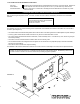
DIAGRAM E DIAGRAM D NOTE: For mounting on vinyl or lap siding a wood frame with 1” x 1 1/2” on the sides and top and 1” x 2” material on bottom can be utilized on exterior wall. This will provide a flush mounting surface for the hood and a nicely finished look with “J” channel when siding. Inside of frame opening should be 8 3/8” wide by 8” high. 9. Connect the Plenum to the Vent Hood of the SideShot following the steps on pages 8, 9 and 10. 10.
NOTCH BRACING It is recommended and local codes may dictate that the joist be reinforced as outlined below. Bracing of the rim joist is not necessary. 1. Cut two 2 x 4 pieces of wood 28 inches in length. 2. Center both pieces on each side of the floor joist above the notch and drive 8 16D or larger nails into each piece, (See Diag. H) DIAGRAM H CONNECTING THE PLENUM TO THE VENT HOOD NOTE: Cut any nails which are protruding downward from the subfloor that may come in contact with the SideShot.
DIAGRAM J IMPORTANT: Adjust SS1 mounting bracket for a slight downward pitch towards exit terminal. INSTALLATION OF VENT PIPE If installing the SideShot Vent System on an oil or gas appliance which is not equipped with a draft hood or draft diverter, a barometric draft control must be used. Install the barometric draft control as shown, (See Diagram K). The SideShot Vent System is designed to accept all brands of 6" single wall, Type "B", Class "A" or Type "L" vent pipe.
4. Using a tube cutter, cut the sensing tube 2" from the elbow directed at the vent pipe inlet collar, (See Diagram L). Discard the cut off section of metal tube. 5. Attach the vent pipe inlet collar to the rear inlet port making sure that the sensing tube is orientated as shown, (See Diagram M). NOTE: Alignment marks on the inlet collar and plenum casing must match. DIAGRAM L DIAGRAM M 6. Attach 90o compression fitting to the short tube on the inlet collar. 7.
ELECTRICAL WIRING All wiring from the SS1 to the appliance must be appropriate Class 1 wiring as follows: installed in rigid metal conduit, intermediate metal conduit, rigid non-metallic conduit, electrical metallic tubing, Type MI Cable, Type MC Cable, or be otherwise suitably protected from physical damage. IMPORTANT: MORE THAN ONE INTERLOCK METHOD MAY BE APPLICABLE In many cases it is easier to interlock with the thermostat/aquastat portion of the heater control circuit vs.
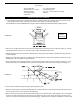
SIDESHOT WITH INTEGRAL UC1 UNIVERSAL CONTROL CONNECTED TO A HONEYWELL R8184 SERIES OR EQUIVALENT PRIMARY CONTROL CONNECT TO L1 OR B1 IMPORTANT: RED JUMPER POSITION MUST BE THE SAME AS APPLIANCE INTERLOCK VOLTAGE.
SIDESHOT WITH INTEGRAL UC1 UNIVERSAL CONTROL CONNECTED WITH AN AQUASTAT IMPORTANT: RED JUMPER POSITION MUST BE THE SAME AS APPLIANCE INTERLOCK VOLTAGE. AQUASTAT C2 D/N 9183046-7 B1 24V L2 115 VAC DRY C1 115V L1 LEGEND: CALL JUMPER B2 J1 L1 XL SUPPLY 115 VAC 50/60 Hz XN R LINE VOLTAGE OIL BURNER PRIMARY CONTROL, BURNER RELAY OR GAS VALVE GROUND UNIVERSAL CONTROLLER J2 N IMPORTANT: CRIMP GROUND WIRE TO GROUNDING SPADE TERMINAL IN ELECTRICAL BOX.
SIDESHOT WITH INTEGRAL UC1 UNIVERSAL CONTROL CONNECTED TO AN OIL-FIRED FURNACE WITH A HONEYWELL T87 OR EQUIVALENT NON-POWERED THERMOSTAT IMPORTANT: RED JUMPER POSITION MUST BE THE SAME AS APPLIANCE INTERLOCK VOLTAGE. SUPPLY 115 VAC 50/60 Hz F R F HONEYWELL R8184 SERIES OR EQUIVALENT GROUND XN W DRY T O XL WHITE T B J1 FACTORYWIRED ORANGE IMPORTANT: REMOVE JUMPER TO AVOID BACKFEEDS OR SHORT CIRCUITS.
SIDESHOT WITH INTEGRAL UC1 UNIVERSAL CONTROL CONNECTED WITH A SINGLE ZONE 24 VAC THERMOSTAT IMPORTANT: RED JUMPER POSITION MUST BE THE SAME AS APPLIANCE INTERLOCK VOLTAGE. G W CALL JUMPER G C J1 Y W XL SUPPLY 115 VAC 50/60 Hz XN R GROUND UNIVERSAL CONTROLLER J2 R INTERNAL CONTROL OF FURNACE DRY Y R 24V 115V THERMOSTAT LEGEND: 115 VAC 24 VAC IMPORTANT: CRIMP GROUND WIRE TO GROUNDING SPADE TERMINAL IN ELECTRICAL BOX. D/N 9183046-5 1.
SIDESHOT WITH INTEGRAL UC1 UNIVERSAL CONTROL CONNECTED WITH A 24 OR 115 VAC STANDING PILOT IMPORTANT: RED JUMPER POSITION MUST BE THE SAME AS APPLIANCE INTERLOCK VOLTAGE. INTERNAL CONTROLS OF FURNACE/BOILER 24V B1 HOT DRY Aquastat T-stat 115V B2 COM CALL JUMPER J1 XN 24V OR 115V GAS VALVE XL HOT TH GROUND UNIVERSAL CONTROLLER J2 COM TR SUPPLY 115 VAC 50/60 Hz LEGEND: 115 VAC IMPORTANT: CRIMP GROUND WIRE TO GROUNDING SPADE TERMINAL IN ELECTRICAL BOX. 24 OR 115 VAC D/N 9183046-1 1.
DRAFT ADJUSTMENT PROCEDURE FOR OIL EQUIPMENT The SideShot Vent system will properly vent a wide range of BTU/hr. input capacities. To compensate for different burner capacities, vent connector lengths and wind conditions it features a draft adjustment located on the outside of the Vent Hood. In general, positioning the draft adjustment inward will cause the SideShot to operate at lowest capacity. Positioning the draft adjustment outward will cause the SideShot to operate at highest capacity.
IMPORTANT: The following paragraph describes the initial draft adjustment. It may be necessary to make a slight readjustment to compensate for various conditions: wind, vent connector resistance, negative building pressure and multiple appliances. ASHRAE lists the average design factor for wind loads in North America at 15 MPH. Refer to the Draft Adjustment Chart on Page 17. We recommend that the 25 MPH category be used to allow for excursions beyond the 15 MPH average.
TROUBLESHOOTING OIL ODORS Many problems can be eliminated quite easily by having the equipment properly set up by a professional oil-heat service contractor. The sophistication of today's heating equipment and instrumentation needed for efficient operation requires proper training. There is no substitute for the work of a qualified oil-heat service professional. All trouble shooting recommendations that follow assume the equipment is installed and maintained by a qualified service person.
LED FAULT INDICATORS Fault conditions are indicated by counting the number of times LED #4 (Red) flashes. LED #4 Flashes 2 Times LED #4 Flashes 3 Times* LED #4 Flashes 4 Times* LED #4 Flashes 5 Times* Fan Prover was in electrically closed position prior to venter operation. Fan Prover does not close within 60 seconds after call for heat. Fan Prover did not re-close after 10 minutes of Venter operation. Fan Prover opened for more than 10 seconds during burner cycle but closed within 10 minutes.
Voltage should be the same in both cases, if not rewire per appropriate diagram or confirm burner control(s) are functioning properly. NOTE: If a different voltage source is provided to terminal 3 which is switched to terminal 4 or when using the A-B dry contacts, voltage measurements may not apply. No, LED #2 (Green) is not lit: Remove power from UC1 and verify dip switch #9 is up or “on” to deactivate Fan Prover status check. Remove P1 and P2 prover leads off of Fan Prover switch and jumper together.
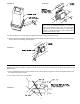
WHEEL REPLACEMENT (DIAGRAM N) 1. Loosen set screw from wheel hub by using a 5/32” allen wrench. 2. Twist wheel to loosen and pull off of motor shaft. Do not pull too hard; wheel may bend. Wheels “fused” to shaft may require penetrating oil and/or a wheel puller to facilitate removal. 3. Slide new wheel on to flat of shaft and firmly tighten set screw. MOTOR OILING The SideShot motor is permanently lubricated and requires no oiling. HOW TO OBTAIN SERVICE ASSISTANCE 1.