REV. C 02/04 TJERNLUND PRODUCTS, INC. 1601 Ninth Street • White Bear Lake, MN 55110-6794 PHONE (800) 255-4208 • (651) 426-2993 • FAX (651) 426-9547 Visit our web site • www.tjernlund.com VERSION X.04 INCLUDES NEW UC1 UNIVERSAL CONTROL MODEL SS1C INSTALLATION INSTRUCTIONS ! Recognize this symbol as an indication of important Safety Information! OWNER INSTRUCTIONS, DO NOT DESTROY NOTE: FLUE GAS TEMPERATURES MUST NOT EXCEED 301oC (575oF) AT VENT SYSTEM INLET.
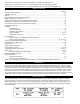
Tjernlund Products welcomes your comments and questions. Address all correspondence to: Customer Service • Tjernlund Products, Inc. • 1601 Ninth Street • White Bear Lake, MN 55110-6794 Call us toll free at 800-255-4208, visit our web site @ www.tjernlund.com or email us at fanmail@tjfans.com. TABLE OF CONTENTS Page (s) Description and Specifications ....................................................................................................................................
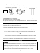
SPECIFICATIONS Motor: 115/1/60, 3300 RPM, 212 watts, 2.28 FLA Fan Proving Switch: Non-adjustable, N/O with a set point of -.04" W.C. High Limit: Manual reset, N/C contacts, open at 79oC (175oF) + 8oC (15oF) UC1 Universal Control: See UC1 Universal Control Board Features on page 4. Pre-Purge: Options (0, 5, 20, 35 seconds); Post-Purge: Factory set at 2 minutes, Options (0, 30 seconds or 1, 2, 4, 8, 16 minutes). See Page 5 for Pre / Post-purge options.
The SS1C must be installed by a qualified installer (an individual properly licensed and/or trained) in accordance with all local codes or, in their absence, in accordance with “The National Building Code of Canada” CSA Std B139 & “The Canadian Electrical Code” CSA Std C22.1. Failure to install, maintain and/or operate the SS1C in accordance with manufacturer's instructions may result in conditions which can produce bodily injury and property damage. 1. The installer must verify that the BTU/hr.
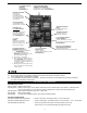
SS1C WITH INTEGRAL UC1 UNIVERSAL CONTROL BOARD FEATURES C, GND, F AUXILIARY DEVICE COMMUNICATION TERMINALS 2 mA @ 5VDC. For Tjernlund MAC1E or MAC4E auxiliary devices. SEE WARNING # 1. P1 - P2 SAFETY CIRCUIT TERMINALS 1 mA @ 5VDC. SEE WARNING # 1. DIP SWITCH SETTINGS Pre-Purge (1-2) Post-Purge (3-8) Prover status check (9) See “Pre / Post Purge & Prover Status Check Dip Switch Settings”. P1 P2 LED STATUS LIGHTS See “LED Status & Fault Indicator Section” for details.
LED FAULT INDICATORS Fault conditions are indicated by counting the number of times LED #4 (Red) flashes. LED #4 Flashes 2 Times LED #4 Flashes 3 Times* LED #4 Flashes 4 Times* LED #4 Flashes 5 Times* Fan Prover was in electrically closed position prior to venter operation. Fan Prover does not close within 60 seconds after call for heat. Fan Prover did not re-close after 10 minutes of Venter operation. Fan Prover opened for more than 10 seconds during burner cycle but closed within 10 minutes.
P1 & P2 PRE-CYCLE FAN PROVER STATUS CHECK Pre-Cycle Prover Status Check Deactivated 9 The Pre-Cycle Prover Status Check is deactivated from the factory on the SS1C. Because of the low set point of the SS1C Fan Prover (as low as .03" w.c.) cross winds may cause the Fan Prover to close prior to a call for heat. Activating the Prover Status Check on the SS1C may cause nuisance lockouts.
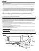
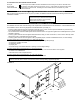
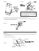
INSTALLATION Tools required: • Reciprocating Saw • Drill and 1/8", 1/4", 1/2" Bits • Blade Screwdriver • Wire Cutter/Stripper • Tube Cutter • 1/2", 7/16",5/8" Wrench • 1/4" Masonry Drill Bit • 1/4", 5/16”, 11/32" Nut Runner or Socket • Hammer INSTALLING VENT HOOD TERMINUS 1. a) Fold template A (Page 25) along dashed line and attach in between the floor joists ensuring that it is snug against the sill plate and right hand floor joist. Follow same procedure if floor trusses are used, (See Diagram B).
DIAGRAM E DIAGRAM D NOTE: For mounting on vinyl or lap siding a wood frame with 1” x 1 1/2” on the sides and top and 1” x 2” material on bottom can be utilized on exterior wall. This will provide a flush mounting surface for the hood and a nicely finished look with “J” channel when siding. Inside of frame opening should be 8 3/8” wide by 8” high. 9. Connect the Plenum to the Vent Hood of the SideShot following the steps on pages 8, 9 and 10. 10.
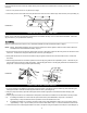
NOTCH BRACING It is recommended and local codes may dictate that the joist be reinforced as outlined below. Bracing of the rim joist is not necessary. 1. Cut two 2 x 4 pieces of wood 71 cm (28 inches) in length. 2. Center both pieces on each side of the floor joist above the notch and drive 8 16D or larger nails into each piece, (See Diag. H) 71cm DIAGRAM H CONNECTING THE PLENUM TO THE VENT HOOD NOTE: Cut any nails which are protruding downward from the subfloor that may come in contact with the SideShot.
DIAGRAM J IMPORTANT: Adjust SS1C mounting bracket for a slight downward pitch towards exit terminal. INSTALLATION OF VENT PIPE A barometric draft control must be used. Install the barometric draft control as shown, (See Diagram K). The SideShot Vent System is designed to accept all brands of 6" single wall, Class "A" or Type "L" vent pipe. Type “B” is not suitable for the SS1C. The vent pipe used must be in compliance with local codes and the listing of the vent pipe manufacturer.
4. Using a tube cutter, cut the sensing tube 2" from the elbow directed at the vent pipe inlet collar, (See Diagram L). Discard the cut off section of metal tube. 5. Attach the vent pipe inlet collar to the rear inlet port making sure that the sensing tube is orientated as shown, (See Diagram M). NOTE: Alignment marks on the inlet collar and plenum casing must match. DIAGRAM L DIAGRAM M 6. Attach 90o compression fitting to the short tube on the inlet collar. 7.
ELECTRICAL WIRING All wiring from the UC1 to the appliance must be appropriate Class 1 wiring as follows: installed in rigid metal conduit, intermediate metal conduit, rigid non-metallic conduit, electrical metallic tubing, Type MI Cable, Type MC Cable, or be otherwise suitably protected from physical damage. IMPORTANT: MORE THAN ONE INTERLOCK METHOD MAY BE APPLICABLE In many cases it is easier to interlock with the thermostat/aquastat portion of the heater control circuit vs.
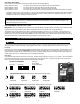
SIDESHOT WITH INTEGRAL UC1 UNIVERSAL CONTROL CONNECTED TO A HONEYWELL R8184 SERIES OR EQUIVALENT PRIMARY CONTROL CONNECT TO L1 OR B1 IMPORTANT: RED JUMPER POSITION MUST BE THE SAME AS APPLIANCE INTERLOCK VOLTAGE.
SIDESHOT WITH INTEGRAL UC1 UNIVERSAL CONTROL CONNECTED WITH AN AQUASTAT IMPORTANT: RED JUMPER POSITION MUST BE THE SAME AS APPLIANCE INTERLOCK VOLTAGE. AQUASTAT C2 D/N 9183046-7 B1 24V L2 115 VAC DRY C1 115V L1 LEGEND: CALL JUMPER B2 J1 L1 XL SUPPLY 115 VAC 50/60 Hz XN R LINE VOLTAGE OIL BURNER PRIMARY CONTROL, BURNER RELAY OR GAS VALVE GROUND UNIVERSAL CONTROLLER J2 N IMPORTANT: CRIMP GROUND WIRE TO GROUNDING SPADE TERMINAL IN ELECTRICAL BOX.
SIDESHOT WITH INTEGRAL UC1 UNIVERSAL CONTROL CONNECTED WITH A SINGLE ZONE 24 VAC THERMOSTAT IMPORTANT: RED JUMPER POSITION MUST BE THE SAME AS APPLIANCE INTERLOCK VOLTAGE. G W CALL JUMPER G UNIVERSAL CONTROLLER J2 R C J1 Y W SUPPLY 115 VAC 50/60 Hz XL INTERNAL CONTROL OF FURNACE DRY Y R 24V 115V THERMOSTAT XN R GROUND LEGEND: 115 VAC 24 VAC IMPORTANT: CRIMP GROUND WIRE TO GROUNDING SPADE TERMINAL IN ELECTRICAL BOX. D/N 9183046-5 1. Connect W from t-stat to #1 on terminal block of UC1.
SIDESHOT WITH INTEGRAL UC1 UNIVERSAL CONTROL CONNECTED WITH A HONEYWELL R8184 SERIES OR EQUIVALENT PRIMARY CONTROL AND A BURNER MOTOR POST-PURGE CONNECT TO L1 OR B1 BLACK ORANGE WHITE THERMOSTAT B T O T W F IMPORTANT: RED JUMPER POSITION MUST BE THE SAME AS APPLIANCE INTERLOCK VOLTAGE.
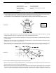
DRAFT ADJUSTMENT PROCEDURE NOTES: All draft adjustments are approximate. This chart is to be used for initial draft adjustment only. Subsequent draft adjustments may be required to compensate for various field conditions: wind, vent pipe resistance, building pressure, multiple appliances, etc. BTU/HR input ratings assume 30% or less excess air for flame retention burners and 50% to 100% excess air for conventional oil burners. Do not exceed the recommended BTU/HR input range of the SideShot.
6. Perform a smoke test and make any adjustments to the burner air shutter, SS1C draft control on the vent hood or the barometric draft control to arrive at a trace of smoke (between 0 and 1) at a minimum over fire draft of -.02” W.C.. 7. Perform a CO2 test at the same location as the smoke test. Reduce the CO2 1% to 2% by opening the burner air shutter. Recheck over fire draft and increase venter draft or adjust barometric damper closed (more draft) if necessary to maintain a minimum of -.02” W.C..
REMINDER : The most significant preventer of wind-induced air infiltration is choosing a proper termination location of the SideShot before installation, see requirements on page 6, under "Vent Hood Termination Clearances."V Verify that the Draft Adjustment is appropriate for the BTU/hr input, as shown on the "Draft Adjustment Chart," page 17. If necessary, change setting by loosening both nuts on each side of the Vent Hood and center both indicators to the desired setting.
CHECKING MEMORY FOR LAST FAULT CODE IMPORTANT: Prior to accessing the fault code memory, note the settings of the dip switches so that they can be returned to their original Pre / Post-Purge positions. When power is supplied to the UC1 use caution when moving dip switches. The last fault code can be retrieved at any time by setting all dip switches 1-8 to the up, or “on” position. The last fault code, or lack there of, will be indicated by counting the number of times LED 4 flashes.
NOTE: Insufficient post-purge may cause limit to trip. If the limit switch trips, verify that the post-purge setting is long enough to remove residual heat from the combustion chamber. If high limit trips repeatedly, do not operate the heater until the source of excessive heat has been determined and repaired. If high limit will not reset and has an open circuit, replace high limit part number 950-0740. Verify inlet assembly sensing tube is clean.
WHEEL REPLACEMENT (DIAGRAM N) 1. Loosen set screw from wheel hub by using a 5/32” allen wrench. 2. Twist wheel to loosen and pull off of motor shaft. Do not pull too hard; wheel may bend. Wheels “fused” to shaft may require penetrating oil and/or a wheel puller to facilitate removal. 3. Slide new wheel on to flat of shaft and firmly tighten set screw. MOTOR OILING The SideShot motor is permanently lubricated and requires no oiling. HOW TO OBTAIN SERVICE ASSISTANCE 1.
TJERNLUND LIMITED TWO YEAR WARRANTY Tjernlund Products, Inc. warrants to the original purchaser of this product that the product will be free from defects due to faulty material or workmanship for a period of (2) years from the date of original purchase or delivery to the original purchaser, whichever is earlier. Remedies under this warranty are limited to repairing or replacing, at our option, any product which shall, within the above stated warranty period, be returned to Tjernlund Products, Inc.