
Owner's manual


3.9 Rear Panel.
The rear panel connectors are identified in Fig.3. Make sure that all settings,
mains and audio connections have been made as described above before
attempting to operate the equipment.
4. OPERATION
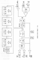
4.1 Front Panel.
The front panel controls are identified in Fig.2.
4.2 Line Input.
A line level signal should already be at about the correct operating level, but
check that the input level switch is correctly set (see section 3.2). An input gain
adjustment may be made if necessary.
4.3 Instrument Input.
The front panel instrument input socket is suitable for low-level sources such
as dynamic microphones, pick-ups or passive guitars and higher level sources
such as active guitars and keyboards. The instrument gain is controlled by the
5013 input gain control. Due to the wide range of the input, a high level of gain
is available in the equaliser, and care should be taken not to apply excessive
input gain to a high level signal. Please note also that the instrument input is
not designed to accept the output of a power amplifier, such as that from a
guitar backline amp.
4.4 Drive and Peak LEDs.
The yellow Drive LED provides a visual indication of the signal level through
the valve stages, and therefore the extent of “warming” or valve character
being introduced. The drive LED will gradually illuminate as the input level or
gain is increased, over the range 0dB to +12dB.
The red Peak LED operates as a conventional warning that clipping is about to
occur. The operating level of the entire signal chain is monitored, and the LED
illuminates when there is less than 5dB of headroom remaining. Normal