
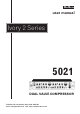
Instruction Manual


3.5 Instrument Input.
Each channel has a 0.25” jack socket on the front panel (see Figure 2). A 2
pin (mono) jack plug is required, which should be wired as follows:
- Tip = Signal Phase (“+” or “hot”),
- Screen = Ground.
3.6 Balanced Output.
The output is via a balanced, 3 pin male XLR connector. The mating connector
should be wired as follows:
- Pin 1 = Ground (screen).
- Pin 2 = Signal Phase (“+” or “hot”).
- Pin 3 = Signal Non-Phase (“-” or “cold”).
3.7 Unbalanced Output.
An unbalanced line output is provided for each channel, on a 0.25” mono jack
socket.
- Tip = Signal Phase (“+” or “hot”).
- Screen = Ground.
3.8 Sidechain Insert Point.
The insertion point is provided on a 3 pin, 0.25” switched jack socket on the
rear of the unit. The pin connections are:
- Sleeve = Ground.
- Tip = Send.
- Ring = Return.
The insertion point is unbalanced, and operates at a nominal level of -2dBu. If
used as an additional send only (e.g. as a send to a tape machine or monitor