T L Audio User Manual Ebony Series A4 Summer TL Audio Limited, Letchworth, England. Tel 01462 492090, Fax 01462 492097. www.tlaudio.co.uk email: info@tlaudio.co.
CONTENTS. CONTENTS. ...................................................................................................................................................2 INTRODUCTION..........................................................................................................................................3 WHY CLASS-A? ............................................................................................................................................4 WHY TUBES? .........................
INTRODUCTION Thank you for purchasing the Ebony A4 Summer. The TL Audio Ebony Series of audio processors are a sleek looking range of discrete Class A processors designed to heighten your audio experience; they use signal paths constructed from discrete transistor “Class A” circuits, with switchable variable drive tube stages, putting you in control of how ‘creamy’ or how ‘cool’ your unit sounds.
Why Class-A? Class A circuits are designed with a constant current flowing through all of the transistors, which is sufficient to drive the peak output required from each block of the circuit. This ensures that every transistor is kept at its optimum operating point, minimising non-linearities due to changes in current and internal thermal effects, and eliminating the objectionable “cross-over” distortion typical of class AB circuits.
A correctly designed balanced interface should have both phase and non-phase signals of equal magnitude (and source impedance), but should allow either of the phase and non-phase signals to be connected to an arbitrary electrical point (e.g. ground) without changing the differential level. Therefore, if, for instance, the non-phase signal is shorted to ground by an unbalanced input on a piece of equipment, then the phase signal should double in magnitude to compensate.
PRECAUTIONS The TL Audio Ebony Summer requires very little installation, but like all electrical equipment, care must be taken to ensure reliable, safe operation.
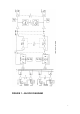
FIGURE 1 – BLOCK DIAGRAM 7
INSTALLATION AC Mains Supply. The unit is fitted with an internationally approved 3 pin IEC connector. A mating socket with power cord and mains plug is supplied. All mains wiring should be performed by a qualified electrician with all power switched off, and the earth connection must be used.
- Ring = Ground ( or connect screen and ring together ) Note: When using unbalanced connection on 3 pin plugs, the ring must be linked to the sleeve to avoid possible reduction in level and/or increase in noise.
unbalanced connections, for example using unbalanced sends and balanced returns, with no loss in level. Balanced XLR Outputs. The outputs are via balanced, 3 pin male XLR connectors. The mating connectors should be wired as follows: - Pin 1 = Ground (screen), - Pin 2 = Signal Phase (“+” or “hot”), - Pin 3 = Signal Non-Phase (“-” or “cold”). If an unbalanced output is required, pins 1 and 3 should both be connected to ground. Level Selection.
OPERATION. Input Gain stage The input gain is set to mirror the line level signal fed into the channel, upon input the signal is a true representation of the input from your console or DAW. Channel Pan Control A pan control is present for each input channel to control the stereo position of the signal fed into it, this is ideal for combining stereo and mono feeds on different channels. Input switching Input switches are located on the left hand side of the front panel.
Insertion Points A balanced master insert point is provided on the back panel. This would be ideal to use with a stereo compressor / EQ or dedicated mastering processor to give a complete back end and mix down / mastering solution. An insert bypass button is also provided on the front panel of the unit to quickly and easily A/B anything you do on the additional outboard equipment inserted. Output Gain. This controls the level of the Ebony A4 output and the level of the summed signal.
SPECIFICATIONS Inputs: Balanced, via 3 pin TRS jack, or 25pin D-Sub per 8 channels. Input impedance: greater than 10Kohm. Nominal Level +4dBu or -10dBu, switched in banks of 8 channels. Pan Controls: -3dB at centre. Attention when panned fully left or right: 60dB. Tube Stage: Switchable tube stage on stereo mix, pre insertion point. “Warmth” control varies THD from typically 0.3% to 10%, predominately second harmonic. Insertion Point: Balanced, via separate 3 pin TRS jack send and return.
Dimensions: 2U, rack mounting or free-standing. 483mm W x 220mm D x 88mm H (19.0” x 7.9” x 3.5”approx). Shipping weight: 6Kg. Power Requirements: Internally set to 230V 50Hz or 115V 60Hz operation. Detachable IEC power cord. Power consumption: 36VA. These specifications are typical figures, subject to normal production tolerances. They do not represent guaranteed limits for any particular piece of equipment. Specifications are subject to change without notice.
SERVICE Should the unit require service, it must be taken or posted to an authorised dealer with a description of the fault. Please retain the original packing for possible future use, and ensure the unit is suitably protected during transit. The manufacturer cannot accept responsibility for damage caused during transportation. This equipment is supported by a limited warranty for a period of one year from the date of purchase.