MATRIX MODE (Version 3.10) INSTALLATION AND OPERATING INSTRUCTIONS 9000 SERIES AMPLIFIERS M-9000 A-9060DH A-9120DH A-9120DL A-9060S A-9120S A-9240SH This manual is intended for those who use the 9000 Series Amplifier in the Matrix mode. For use in the Mixer mode, please read the separate instruction manual for the Mixer mode. Thank you for purchasing TOA's 9000 series Amplifier. Please carefully follow the instructions in this manual to ensure long, trouble-free use of your equipment.
TABLE OF CONTENTS 1. IMPORTANT SAFETY INSTRUCTIONS ........................................................... 6 2. SAFETY PRECAUTIONS ....................................................................................... 7 3. GENERAL DESCRIPTION .................................................................................... 9 4. FEATURES ............................................................................................................... 10 5. INSTALLATION PRECAUTIONS ......................
9.2. Zone Paging 9.2.1. Paging port mode ......................................................................................... 30 9.2.2. Ring signal mode ......................................................................................... 31 9.3. Releasing Key Lock ............................................................................................... 32 10. PAGING WHILE POWER IS OFF ...................................................................... 33 11.
15. MODULE INSTALLATION 15.1. 15.2. 15.3. 15.4. Module Combination ............................................................................................ 88 Channel Numbers and Terminal Numbers ........................................................... 88 Module Installation ............................................................................................... 88 Module Installation Examples .............................................................................. 90 16.
24. SIGNAL FLOW DIAGRAM ................................................................................ 118 25. LEVEL DIAGRAM ................................................................................................. 119 26. SPECIFICATIONS 26.1. 26.2. 26.3. 26.4. 26.5. 26.6. M-9000 ............................................................................................................... 120 A-9060DH, A-9120DH .....................................................................................
1. IMPORTANT SAFETY INSTRUCTIONS • Read these instructions. • Keep these instructions. • Heed all warnings. • Follow all instructions. • Do not use this apparatus near water. • Clean only with dry cloth. • Do not block any ventilation openings. Install in accordance with the manufacturer's instructions. • Do not install near any heat sources such as radiators, heat registers, stoves, or other apparatus (including amplifiers) that produce heat.
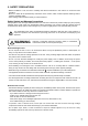
2. SAFETY PRECAUTIONS • Before installation or use, be sure to carefully read all the instructions in this section for correct and safe operation. • Be sure to follow all the precautionary instructions in this section, which contain important warnings and/or cautions regarding safety. • After reading, keep this manual handy for future reference.
CAUTION Indicates a potentially hazardous situation which, if mishandled, could result in moderate or minor personal injury, and/or property damage. When Installing the Unit • Never plug in nor remove the power supply plug with wet hands, as doing so may cause electric shock. • When unplugging the power supply cord, be sure to grasp the power supply plug; never pull on the cord itself. Operating the unit with a damaged power supply cord may cause a fire or electric shock.
3. GENERAL DESCRIPTION TOA's 9000 Series Amplifiers are Matrix Mixers designed to be used in conjunction with optional modules and can be configured for up to 8 inputs and 8 outputs. Usable modules include 5 types of 9000 series plug-in modules, D-001T (2-channel input), T-001T (Audio output expansion), C-001T (Control I/O expansion), ZP001T (Zone paging), and AN-001T (Ambient noise sensor), as well as 900 series input modules. The most appropriate modules can be selected depending on applications.
4. FEATURES • Either matrix or mixer mode can be selected depending on application for optimum operation. • Matrix mode is suitable for BGM broadcasts or paging to zoned areas. • Mixer mode is suitable for speech or sound reinforcement in such applications as hotel meeting rooms, churches or conference rooms. • Eight module slots enable audio input and output configuration ranging from 1 input and 1 output to 8 inputs and 8 outputs.
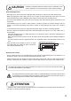
5. INSTALLATION PRECAUTIONS • Keep the 9000 Series Amplifiers except the M-9000 over 10 cm away from objects that may obstruct air flow to prevent the unit's internal temperature rise. Over 10 cm INPUT SELECT 1 2 3 4 5 INPUT VOLUME ON/OFF ON/OFF OUTPUT VOLUME MEMORY PARAMETER POWER UTILITY 6 ENTER OUTPUT SEL 7 ESC/BACK 8 Over 10 cm Over 10 cm • When mounting the unit on an equipment rack · Use the supplied rack-mounting bracket. (For the bracket attachment, refer to p. 100.
7. NOMENCLATURE AND FUNCTIONS 7.1. M-9000 (Matrix Mixer Amplifier), A-9060DH/9120DH/9120DL/9060S/9120S/9240SH (Matrix Mixer Power Amplifiers) [Front] This figure represents the M-9000. INPUT SELECT 1 2 3 4 INPUT VOLUME 5 ON/OFF ON/OFF OUTPUT VOLUME MEMORY PARAMETER POWER UTILITY 6 ENTER OUTPUT SEL 7 TOA 9000 SERIES PRE-AMPLIFIER M-9000 ESC/BACK 8 2 3 4 5 6 7 8 10 9 1. Power switch and Power indicator Press this switch to turn on the power. The power indicator lights.
[VFD on-screen indications] 15 16 17 18 19 dB k Hz m sec GAIN COM FAULT FADER LEVEL 20 21 22 1 2 3 4 5 dB 6 7 Q 8 FREQ KEYLOCK EMERGENCY OL 0 –10 –20 –30 –40 TONE LOUD EQ COMP 23 26 2 6 3 7 4 8 OL 0 –10 –20 –30 –40 GATE DUCK NOM DELAY 27 30 3 24 1 5 FADER LEVEL 31 32 5 25 28 29 15. 14-Segment,18-digit alphanumeric display Displays the corresponding setting screen or data when each function key is pressed. Parameters being edited flash. 24.
29. Output channel ON/OFF indicator (channel number) Lights when the corresponding output is on (i.e. in operation mode), and flashes when off. The number of channels of which indicators light depends on the modules used. 31. Output level indication Scale of levels (in dB) for the output meter. 32. Output meter status indicator Indicates which the output level (LEVEL) or output fader position (FADER) is being displayed on the output meter (30). 30.
[Changing the indicated channels on the LEVEL output meter] The output meter indicates the signal levels of only a set of 4 channels: CH 1 – 4 (factory-preset) or CH 5 – 8. Pressing the Up shift key alternately switches the level indication between CH 1 – 4 and CH 5 – 8. The LEVEL indicator of the output meter status indicator flashes while the CH 5 – 8 are indicated, and stays lit while the CH 1 – 4 are indicated. In the same manner, the output meter also changes in the Fader indication.
[Rear] • M-9000 120V 60Hz 40W CTRL I/O REMT VOL1 REMT VOL2 IN RS-232C MODE OUT MATRIX MIXER IN E IN E 1 2 3 4 E 1 2 3 4 E H PRE AMP OUT 1 C E H : Hot C : Cold E : Earth H PRE AMP OUT 2 C E M-9000 CU 35 34 37 38 39 40 36 • A-9060DH, A-9120DH, A-9120DL WARNING 120V 60Hz 250 W DO NOT CONNECT NEGATIVE(–) TERMINALS TOGETHER. SP OUT + – + – 41 CTRL I/O REMT VOL1 REMT VOL2 70V OUT 1 CLASS 2 WIRING IN 70V OUT 2 RS-232C MODE OUT MATRIX MIXER This figure represents the A-9120DH.
33. Speaker output terminal Connects speakers of which total impedance matches the amplifier's output impedance. (Refer to p. 95 "Speaker Output Terminal Connections.") 34. AC inlet Connects the supplied power cord. 35. RS-232C serial communication port Connector for communications with a personal computer or control equipment. 36. Functional earth terminal Hum noise may be generated when external equipment is connected to the unit.
7.2. Optional Modules 7.2.1. D-001T (2-Channel Input Module) The D-001T module is designed for use with the 9000 Series amplifiers. Up to 4 modules (8 channels in total) can be inserted into the amplifier. The module can handle signals ranging from microphone level (–60 dB) to line level (–10 dB) in 9 input sensitivity levels. Phantom power (24 V) can be supplied for microphone level (–60 dB to –30 dB) signals. The D-001T module has an internal digital signal processor that can process input signals.
7.2.3. ZP-001T (Zone Paging Module) The ZP-001T module is designed for use with the 9000 Series amplifiers and functions as an interface to connect the 9000 Series amplifiers to an analog PABX, allowing zone paging to be initiated from the PABX. Only one ZP-001T module can be used per 9000 Series amplifier. There are two operation modes: Ring signal and Paging port modes. Select one of the two modes when using this module. The operation method differs depending on the set operation mode. (Refer to p.
7.2.4. C-001T (Control I/O Expansion Module) The C-001T module is designed for use with the 9000 Series amplifiers and can provide up to 8 channels each of input and output expansion. Since the main unit has 4 fixed inputs and outputs each, the control input and output can be expanded to up to 12 channels each when the C-001T module is used. 7. Control input terminal [IN 1, 2, 3, 4, 5, 6, 7, 8, E] 9-pin removable terminal block, 8-circuit control input terminal.
7.3. Optional Accessories 7.3.1. AN-9001 (Ceiling Mount Microphone) The AN-9001 is designed to be mounted in a wall or ceiling with the use of a 1-gang electrical box. It is used in conjunction with the AN-001T Ambient Noise Sensor Input module in the 9000 Series system. [Front] [Side] [Rear] Rel eas e Hot Cold Earth k Loc 1 [Bottom] 1. Microphone output terminal [Hot, Cold, Earth] Electronically-balanced 3P removable terminal block.
7.3.2. ZM-9001 (Zone Manager) The ZM-9001 adds 6 control inputs and can be mounted in a 1-gang electrical box. [Front] 1 [Side] [Rear] 3 2 2 E 3 4 5 6 OUT [Bottom] 2. Control buttons [1 – 6] Activate the function assigned to them when pressed. 3. Control output terminal [E, OUT] Connect this terminal to the 9000 Series amplifier's REMT VOL terminal. Use a shielded cable with 50 Ω or less line resistance (per line) for this connection.
7.3.3. ZM-9002 (Zone Manager) The ZM-9002 adds 4 control inputs and 1 volume control, and can be mounted in a 1-gang electrical box. [Front] [Side] 1 2 3 4 4 [Rear] 6 E OUT 5 0 [Bottom] 4. Control buttons [1 – 4] Activate the function assigned to them when pressed. 5. Volume control Adjusts the volume on the assigned input or output channel. 6. Control output terminal [E, OUT] Connect this terminal to the 9000 Series amplifier's REMT VOL terminal.
7.3.4. SS-9001 (Speaker Selector) The SS-9001 selectively distributes each of 2 inputs to the same 4 output zones. It is used in conjunction with the ZP-001T Zone Paging module. [Left side] [Front] [Right side] 9000 SERIES SPEAKER SELECTOR 7 IN 1 70 V MAX. 240W ZONE 1 11 IN 2 IN 2 70 V MAX. 240W CTRL IN 8 ZONE G ZONE G ZONE G ZONE G ZONE 2 IN 2 1 2 3 4 ZONE 3 IN 2 DC IN 24V 120mA 9 ZONE 4 IN 2 10 7. Speaker input terminals [IN 1, IN 2] 2-pin removable terminal blocks.
8. DESCRIPTION OF MATRIX MODE Two operation modes are made available to the unit: Matrix mode and Mixer mode. Be sure to select the matrix mode by the Mode switch on the rear panel before using the unit. (The mode switch is factory-preset to the matrix mode.) MODE MATRIX MIXER Mode switch Important Be sure to disconnect the power supply plug from the AC outlet when changing the mode.
8.1.2. 1-channel output operation This operation method can be selected when the A-9060S, A-9120S, or A-9240SH Amplifier without T-001T Audio Output Expansion module installed is used. Audio signals are delivered only at the amplifier's output channel 1. Paging calls and BGM broadcasts are made on the basis of the priority levels set for input channels.
8.2. Glossary • ANC (Ambient Noise Control) function (AN-001T only) The ANC function automatically adjusts the amplifier's output volume in response to the change in ambient noise level. The output volume changes as the ambient noise level goes above or below the set reference level. • Ducker function The Ducker function automatically attenuates input signals with lower priority when two or more audio signals are simultaneously received.
9. OPERATION To operate the unit in the matrix mode, make necessary settings in advance such as the audio input/output settings and event settings (including broadcast pattern and BGM broadcast group) according to the set operation method. 9.1. Normal Use In the matrix mode, the unit need not be manually operated in normal conditions since the set broadcast patterns can be activated by means of remote control.
9.1.3. Changing the input volume Step 1. Press the Input channel selection key to choose the input channel for which you want to change the volume from those with the illuminated Input channel ON/OFF indicator (channel number). The selected channel's selection indicator (red dot) lights, and the channel name and volume level are displayed on the VFD screen. Step 2. Adjust the volume using the input volume control.
9.2. Zone Paging This section describes the method of initiating zone paging from a PABX (extension telephone) using the ZP001T Zone Paging module. Note that the operation method differs depending on the ZP-001T's operation mode setting: paging port mode or ring signal mode. In both operation modes, when any of the following situations arises, the ZP-001T will not receive calls from the PABX or the line will be cut off if the ZP-001T is being engaged in paging call.
9.2.2. Ring signal mode Step 1. Make a call from the extension telephone to the ZP-001T module. After a calling tone sounds twice, the ZP-001T receives the call and a callback tone is heard from the handset. Step 2. Select the output channel. Press [0] first, followed by the output channel number* ([1] – [8] or [9] when selecting all numbers simultaneously). Pressing the [#] key completes the output channel selection.
9.3. Releasing Key Lock The key lock function prevents the front-mounted keys or knobs from being tampered. (Refer to p. 77 "Key Lock Function Setting.") You can temporarily operate the locked keys by entering a password to unlock them. Operation after password entry differs depending on the locked keys. Step 1. Press the locked key. The password entry screen is displayed with the flashing indication of the character entry position on the extreme left.
10. PAGING WHILE POWER IS OFF The 9000 Series amplifiers are designed to initiate paging by way of the ZP-001T module or activate the Event*1 even while the power is OFF*2. The unit operates as follows when the power is switched OFF: • Events*1 by control input (including the C-001T module) can be activated, but those using the VOX (Voice Operated Exchange) function cannot be activated. • The unit returns to Power-OFF state after Event or paging completion.
11. SYSTEM DESIGN-TO-OPERATION FLOW 1. Design the system. 1.1. Determine the input and output equipment. 1.2. Set the input-to-output routing and priority. 2. Prepare equipment. 2.1. Mount modules. (Refer to p. 88.) 2.2. Check to confirm that the Mode switch is set to the matrix mode. (Refer to p. 25.) 2.3. Connect the power source to the unit using the power cord, then turn on the power switch. 3. Perform equipment settings. 3.1. Select the operation method. (Refer to p. 35.) 3.2.
12. SELECTING OPERATION METHOD In the matrix mode, when the unit's power is first turned on after shipment from the factory, there is the case where the operation method can be or cannot be selected. This depends on the 9000 Series amplifier model and its module configuration. When the operation method selection is possible, proceed to the related settings after selection. POWER When AC power is first fed to the unit and the power switch is first turned on after the unit was shipped from the factory.
13. SETTING Ensure that the Mode switch on the unit's rear panel is set to the MATRIX position before performing the setting. The setting items include those which must be set before operation (audio input/output, Event, and utility settings), those which are adjusted while actually monitoring the sound (adjustment mode settings), and those which restrict operations of front panel keys and knobs (key lock settings).
13.2. Setting Keys and Knobs Output channel ON/OFF key Memory key Input channel ON/OFF key Utility menu key [Front] INPUT SELECT 1 2 3 4 5 INPUT VOLUME ON/OFF ON/OFF OUTPUT VOLUME MEMORY PARAMETER POWER UTILITY 6 7 TOA 9000 SERIES AMPLIFIER A-9120DH OUTPUT SEL ENTER ESC/BACK 8 Input channel selection keys Input volume control Output channel selection key Output volume control Screen shift keys Escape/Back key Parameter setting knob Enter key This figure represents the A-9120DH.
13.3. Basic Setting Operation 13.3.1. Entering the setting mode Holding down the Utility menu key for 2 seconds or more displays the setting menu screen. Note You cannot enter the setting mode as long as any indication is displayed in the upper line of the VFD screen. To enter, delete the indication by pressing the Memory key, then hold down the Utility key for 2 seconds or more. Normal use state Setting menu screen UTILITY I NPU T – S E T T I NG 13.3.2.
[Setting content selection] Use the Parameter setting knob in most cases. In some cases, however, use the input and output channel selection keys, or the input and output channel ON/OFF keys. PARAMETER I NPUT 1 PR I OR I T Y 8 I NPUT 1 PR I OR I T Y 1 For example, to select an input channel, use the input channel selection key as shown below. SEL ECT I NPUT CH I N1 – I NPUT 1 INPUT SELECT 1 13.3.3.
13.4. Input Parameter Setting 13.4.1. Setting flow chart [Normal matrix operation] Normal use state MEMORY UTILITY Press for over 2 seconds. PARAMETER Setting menu screen INPUT SELECT 1–8 Input channel selection I NPU T – S E T T I NG SEL ECT I NPUT CH Input channel name setting (p. 42-A1) I N1 – _ _ _ _ _ _ _ ESC/BACK (For the channel on which the D-001T is used) Input sensitivity setting (p.
[1-channel or 2-channel output operation] Normal use state MEMORY UTILITY Press for over 2 seconds. PARAMETER Setting menu screen INPUT SELECT 1–8 Input channel selection I NPU T – S E T T I NG SEL ECT I NPUT CH Input channel name setting (p. 42-A1) I N1 – _ _ _ _ _ _ _ ESC/BACK (For the channel on which the 900 series module is used) (For the channel on which the D-001T is used) Trigger setting (p. 44-A11) Input sensitivity setting (p.
13.4.2. Input setting items Use the Parameter setting knob for each parameter selection. (A1) Input channel name setting I N1 – _ _ _ _ _ _ _ The flashing portion is the cursor position for entering channel name characters. Select a character from the alphanumeric character list by rotating the Parameter setting knob, then move the cursor with the Right shift key. Entering a new name overwrites the existing name, if there is.
(A5) Pre-paging tone ON/OFF setting (when the ZP-001T is used) PRE PAGE T ONE – O F F Set whether or not to sound a one-tone chime before paging. Setting Range ON, OFF (default) When set to OFF, the tone does not sound at the paging telephone, either. (A6) Operation mode setting (when the ZP-001T is used) MODE = PAG I NG POR T Select the method of activating paging.
(A11) Trigger setting (only in the 1-channel or 2-channel output operation, when the 900 series module or D-001T is used) T R I GGER = NONE Set how to activate the selected input channel. Setting Range NONE (default), C-IN01 – 04 (C-IN01 – 12 when C-001T is used), VOX (Selectable only when D-001T is used) (A12) Priority setting (when the AN-001T is not used) I N1 PR I OR I T Y 8 Assign priority levels of 1 – 8 (high to low) to the selected input signals.
13.5. Audio Output Name Setting 13.5.1. Setting flow chart The screen display examples shown below may differ from actual displays. The on-screen indications shown in red here (actually shown by flashing cursors) are parameters or setting contents to be selected with the Parameter setting knob, input channel selection key or other designated keys. The indications of the [ ], [ ], [ ], and [ ] arrows represent that the screen is switched with the Screen shift key.
13.6. Event Setting (Only in the normal matrix operation) 13.6.1. Setting flow chart The screen display examples shown below may differ from actual displays. The on-screen indications shown in red here (actually shown by flashing cursors) are parameters or setting contents to be selected with the Parameter setting knob, input channel selection key or other designated keys. The indications of the [ ], [ ], [ ], and [ ] arrows represent that the screen is switched with the Screen shift key.
13.6.2. Event setting items Unless otherwise specified, use the Parameter setting knob for each parameter selection. (B1) Event number selection EVENT 0 1 NONE Event number Setting Range 01 – 32 (default: 01) (B2) Event classification setting EVENT 0 1 NONE Event classification Setting Range • NONE: • ROUTE: • BGM END: • BASE: NONE (default), ROUTE, BGM END, BASE Invalidates the selected Event. Sets broadcast patterns consisting of input/output, trigger, and other settings.
(B4) Output channel setting (when Event classification is set to ROUTE) EVENT 0 1 OU T 1 Output channel name Setting Range OUT1 – 2, Max. 8 when T-001Ts are used (default: OUT1) Note: 2 or more channels selectable. • Select the output channel using the Output channel selection key. The name of selected output channel is displayed on the screen. Then confirm the selection by setting the Output channel ON/OFF key to ON (the output channel indicator, red dot on the VFD screen lights).
(B7) Busy input terminal setting (when Event classification is set to ROUTE, the Trigger to the control input C-IN terminal, and the Trigger type to PULSE) BUS Y – I N NON E Select the control input terminal to receive Busy signal. Selecting the terminal overwrites the previously set function on it if there is. Setting Range NONE (default), C-IN01 – 04 (C-IN01 – 12 when C-001T is used) Once broadcast is activated by means of a pulse trigger, a signal is needed to terminate the broadcast.
(B11) BGM Event number selection (when Event classification is set to BASE) EVENT 0 1 BAS E 02 EVENT 0 1 BAS E 02 ENTER Event number Setting Range Confirmation indicator 01 – 32 (default: 01) Rotating the Parameter setting knob displays only the priority-8 inputs with the trigger function set to NONE (normally BGM broadcasts) out of the Event numbers with Event classification set to ROUTE.
13.7. Utility Setting 13.7.1. Setting flow chart The screen display examples shown below may differ from actual displays. The on-screen indications shown in red here (actually shown by flashing cursors) are parameters or setting contents to be selected with the Parameter setting knob, input channel selection key or other designated keys. The indications of the [ ], [ ], [ ], and [ ] arrows represent that the screen is switched with the Screen shift key.
From the previous page (P. 55-C1) Function selection (when the control output is selected) UT I L I LY C - OU T PARAMETER Control output number selection (p. 58-C17) C - OU T 0 1 NON E Control output function selection (p. 59-C19) C - OU T 0 1 NON E (When the control output function is set to POWER) (p. 59-C20) C - OU T 0 1 POW ER PARAMETER or Interlock output control display (only in the normal matrix operation) (p.
From the previous page (P. 55-C1) Function selection (when the remote volume control is selected) UT I L I TY REMO T E Remote controller type setting (when the remote controller type is set to VOLUME) (p. 61-C26) REMO T E 1 PARAMETER VO L UME PARAMETER (when the remote controller type is set to ZM-9001) (p. 61-C26) REMO T E 1 (when the remote controller type is set to ZM-9002) (p. 61-C26) ZM - 9 0 0 1 REMO T E 1 ZM - 9 0 0 2 PARAMETER or Remote-controlled channel setting* (p.
From the previous page (P. 55-C1) Function selection (when the operation method is selected) UT I L I TY SUB - MODE Operation method setting (p. 63-C36) MODE MA T R I X PARAMETER or Function selection (when the firmware version is selected) UT I L I TY V ERS I ON Firmware version indication (p. 64-C37) F I RM V E R S I O N = 3 .1 0 PARAMETER or Function selection (when the memory initialization is selected) UT I L I TY MEMORY Memory initialization (p.
13.7.2. Utility setting items Unless otherwise specified, use the Parameter setting knob for each parameter selection.
(C3) Event assignment display (Only in the normal matrix operation) C - I N0 1 EVENT NONE When the displayed control input (C-IN01 in this example) is set to Trigger in the Event setting, the Event number is displayed. If the control input is not set to Trigger, the NONE indication is displayed. Assigning a function to the control input terminal preset to "Event-Trigger" cancels the "Event-Trigger" function, being replaced with the new function.
(C8) (When the control input function is set to MUTE:) C - I N0 1 – MU T E Assign the function that mutes the input or output channel to the control input. Closing the control input terminal mutes the set channel. An input channel, when muted while in use, occupies the routed output, causing the Event-activated broadcast by the input channel with lower priority not to go through to the same output channel. Assigning a function to this terminal overwrites the previously set function on it if there is.
(C13) (When the control input function is set to EMG-MUTE:) C - I N0 1 – EMG - MU T E Assign the function that simultaneously mutes all output channels to the control input. Closing the control input terminal mutes all output channels. This function is used to mute the output provided from the unit during emergency broadcast operation. Assigning a function to this terminal overwrites the previously set function on it if there is.
(C18) Interlock output control display (Only in the normal matrix operation) C - OU T 0 1 EVENT NONE When the displayed control output (C-OUT01 in this example) is designated as interlock output in the Event setting, its Event number is displayed. If not designated as interlock output, the NONE indication is displayed in place of the Event number. (C19) Control output function selection C - OU T 0 1 NON E Sets the functions to be assigned to the control output terminals.
[When the function is set to RS232C:] (C23) Communication speed (bps) setting SER I AL SPEED= Setting Range 5 7. 6 9.6 k, 19.2 k, 38.4 k, 57.6 k (default), 115.
[When the function is set to REMOTE:] (C26) Remote controller type setting REMO T E 1 VO L UME Set the type of remote controller connected to the remote control input terminals. Use the Left and Right shift keys to move the setting items on the screen. Setting Range Remote Volume Terminal Number REMOTE 1, REMOTE 2 Controller type OFF (default), VOLUME, ZM-9001, ZM-9002 • OFF: Select this setting when no remote controller is connected.
[When the function is set to ANC:] (C29) ANC monitor switching ON/OFF setting ANC MON S E L EC T = ON If there are 2 or more ANC inputs, set whether or not ANC inputs to be monitored are switched. Setting Range OFF (default), ON (C30) Monitor switching control input terminal setting (When the ANC monitor switching is set to ON) MON SEL ECT C I N0 1 Select the control input terminal to switch the ANC inputs* to be monitored.
[When the function is set to EVENT:] (Only in the normal matrix operation) (C34) Setting the Event to be recalled when power is switched on POWERON – E V EN T Setting Range LAST LAST (default), 01 – 32 (only for Events set for ROUTE or BASE) Set the Event number to be activated when the unit's power is switched on.
[When the function is set to VERSION:] (C37) Firmware version indication F I RM V E R S I O N = 3 .1 0 Displays the firmware version number. [When the function is set to MEMORY:] (C38) Memory initialization I N I T I AL I ZE OK ? Pressing the Enter key initializes all of the unit's current settings to default settings. To cancel initialization, press the Left shift key or Escape/Back key to revert back to the previous screen.
13.8. Adjustment Mode Setting 13.8.1. Settings in adjustment mode In the adjustment mode, audio setting parameters can be set while monitoring the output sound. Input and output gain settings, input sound source equalization*, and sound equalization for individual output zones can be performed. The setting parameters are individually adjusted for each Event (normal matrix operation) or input channel (1channel or 2-channel output operation).
Step 8. Return to the input gain setting screen and press the Right shift key. The output channel selection and gain setting screen is displayed. Note To stop the audio output temporarily, press the output channel ON/OFF key. :O N + I N1 – I N1 1. 0 8 OU T 1 – OU T 1 : O N + 1 0. 0 OUTPUT VOLUME Step 9. Adjust the gain with the Output volume control. In this event, pressing the Output channel selection key permits the output channel to be selected.
13.8.2. Adjustment mode setting flow chart (Normal matrix operation) Normal use state Event selection (p. 68-D1) E V EN T 0 1 – ROU T E MEMORY PARAMETER UTILITY To turn on, Press for over 2 seconds. PARAMETER Setting menu screen AD J US T INPUT VOLUME ON ON/OFF To select, Output channel selection and Output gain setting (p. 72-D16) Input gain setting (p. 68-D3) To select, I N1 – I N1 :O N (1-channel or 2-channel output operation) Input channel selection (p.
13.8.3. Adjustment mode setting items Unless otherwise specified, use the Parameter setting knob for each parameter selection. (D1) Event selection (In the normal matrix operation) Event activation ON/OFF EVENT 0 1 – ROUT E FAULT 1 2 3 4 5 6 7 8 ON KEYLOCK 1 2 3 4 EMERGENCY 5 6 7 8 Event No. Output channels set in Event setting Input channel set in Event setting Rotate the Parameter setting knob to obtain the Event No. of which settings are desired to be adjusted.
(D4) BASS and TREBLE settings (input/output) BAS S + 1 2 TREBL E – 1 0 Rotate the Parameter setting knob to set gains. Press the Right or Left shift key to select BASS or TREBLE, of which gain value that flashes can be adjusted. –12 dB to +12 dB (default: 0 dB), 1 dB steps Setting Range (D5) Loudness compensation setting (input/output) L OUDNE S S – ON Rotate the Parameter setting knob to set the loudness compensation function ON/OFF. Setting ON boosts low frequencies.
(D8) Compressor setting (input/output) COMPRE S SOR – O F F Setting Range OFF (default), 1, 2, 3, 4, 5 Use the compressor to prevent power amplifier overload or to produce more easily heard sound by averaging the audio level. The number shows the compressor's effectiveness level, which can be set by rotating the Parameter setting knob. • 1 (Peak limiter) Provides a peak limiter function that protects amplifiers and speakers against damage caused by an excessive signal input.
(D11) Highest output level setting (when the AN-001T is used and ANC operation is set to ACTIVE) MAX I MUM LEVEL 0 Set the upper limit of the ANC-activated output level. Setting Range –15, –12, –9, –6, –3, 0 (default) dB Note: Settable level is 3 dB or more above the lower limit (lowest output level). (D12) Sampling time setting (when the AN-001T is used and ANC operation is set to ACTIVE) SAMP L E T I ME 20 Set the required time to measure ambient noise.
(D14) Reference level adjustment (when the AN-001T is used and ANC operation is set to ACTIVE) ANC AD J 0 : SENS ANC adjustment value 8 Reference level Adjust the reference level which is a starting point for detecting the amount of change in ambient noise level. (Refer to the previous setting item.
(D17) Speaker parameter presetting SP EQ ALL FLAT Optimum equalization can be automatically set depending on the type of speaker to be used. If this function is not used or the speaker to be used is not included in a speaker list, set "SP EQ" to ALL FLAT. When the speaker type is selected from the speaker list, the number of bands that can be set on the next EQ setting screen decreases by the number of bands to be used in the setting performed on this screen.
H-1 GAIN (dB) FREQ (Hz) EQ 01 EQ 02 EQ 03 EQ 04 EQ 05 EQ 06 (HPF) EQ 07 EQ 08 EQ 09 EQ 10 (LPF) Q Settable EQ bands in the EQ setting screen – +10 –6.5 +1.5 – 118 125 220 5k 15.8 k 0.707 1.8 1.414 0.305 0.5 H-1SUBWOOFER*2 GAIN (dB) FREQ (Hz) Q Settable EQ bands in the EQ setting screen – +4 –6.5 +1.5 – 118 125 220 5k 15.8 k 0.707 1.8 1.414 0.305 0.
HB-1 GAIN (dB) FREQ (Hz) EQ 01 EQ 02 EQ 03 EQ 04 EQ 05 EQ 06 EQ 07 EQ 08 EQ 09 (HPF) EQ 10 (LPF) 40 100 SW FOR F-122*5 GAIN (dB) FREQ (Hz) EQ 01 EQ 02 EQ 03 EQ 04 EQ 05 EQ 06 EQ 07 EQ 08 EQ 09 (LPF) EQ 10 Q Settable EQ bands in the EQ setting screen – – 1 1 100 112 0.5 0.
FB-120*9 GAIN (dB) FREQ (Hz) EQ 01 EQ 02 EQ 03 EQ 04 EQ 05 EQ 06 EQ 07 EQ 08 EQ 09 (HPF) EQ 10 (LPF) Q Settable EQ bands in the EQ setting screen – – 40 100 2.
13.9. Key Lock Function Setting The key lock function prevents equipment malfunctions by disabling operation of each key. 13.9.1. Keys that can be locked This figure represents the M-9000. INPUT SELECT 1 2 3 4 INPUT VOLUME 5 ON/OFF ON/OFF OUTPUT VOLUME MEMORY PARAMETER UTILITY POWER 6 ENTER OUTPUT SEL 7 TOA 9000 SERIES PRE-AMPLIFIER M-9000 ESC/BACK 8 INPUT OUTPUT UTIL POWER ALL ALL: Locks all keys simultaneously.
13.9.2. Key lock function setting flow chart The screen display examples shown below may differ from actual displays. The on-screen indications shown in red here (actually shown by flashing cursors) are parameters or setting contents to be selected with the Parameter setting knob, input channel selection key or other designated keys. The indications of the [ ], [ ], [ ], and [ ] arrows represent that the screen is switched with the Screen shift key.
13.9.3. Key lock function setting items Set the keys to be locked on the key lock function setting screen. The KEYLOCK indication lights after setting completion. Since a password is requested if the locked key is pressed, enter the password. Unless otherwise specified, use the Parameter setting knob for each parameter selection. (E1) Lock status display (No key is locked.) KE Y L OCK (Any key except the Utility key is locked.
(E7) Output channel selection key lock ON/OFF KE Y L OCKOU T PU T 1 OFF Locks the Output channel selection key, Output channel ON/OFF key, and Output volume control for each Output channel. Select with the Parameter setting knob the Output channel to be locked, and set the key lock function to ON with the Output channel ON/OFF key. The Output channel selection key selects an output channel one by one only in numerical order starting from Channel 1.
13.9.4. Password setting When using a password, set the password before performing lock setting for each key. Step 1. Hold down the Utility menu key for 2 seconds or more in normal use state. The setting screen is displayed. 1 UTILITY Step 2. Select KEYLOCK with the Parameter setting knob. I NPUT – SE T T I G PARAMETER 2 Step 3. Press the Right shift key. Lock status is displayed. KE Y L OCK 3 Step 4. Press the Down shift key. The Password setting screen is displayed.
13.9.5. Key lock setting operation Step 1. Hold down the Utility menu key for 2 seconds or more in normal use state. The setting screen is displayed. UTILITY 1 I NPUT – SE T T I G Step 2. Select KEYLOCK with the Parameter setting knob. PARAMETER 2 KE Y L OCK Step 3. Press the Right shift key. Lock status is displayed. 3 KE Y L OCK UN L OCKED ENTER Step 4. Press the Enter key. The all-key lock ON/OFF setting screen is displayed. KE Y L OCK ALL 4 OFF Step 5. Set keys to be locked. 5-1.
14. RESTORING FACTORY DEFAULT SETTING Follow the procedures below to return all settings to default values while using the unit in the matrix mode. Details of the default values are shown on the next page, "Default Setting Table." Step 1. Hold down the Utility menu key for 2 seconds or more when in normal use state. Step 2. Using the Parameter setting knob, select UTILITY SETTING, then press the Right shift key. Normal operation mode U TILITY 1 Setting menu screen Step 3.
14.1. Default Setting Table 14.1.1.
[When Event classification is set to ROUTE] Input Channel Output Channel Trigger Trigger Type Busy input terminal Interlock Output Control Interlock Output IN1 OUT1 NONE LEVEL (When the trigger setting is C-IN) NONE (When the trigger type setting is PULSE) OFF COUT01 (When the interlock output control is ON) [When Event classification is set to BGMEND] Trigger C-IN01 [When Event classification is set to BASE] Event Number Trigger 01 C-IN01 14.1.4.
[When the function selection is set to REMOTE] Remote Controller Type Remote-Controlled Channel Volume-Controlled Signal OFF REMOTE1 terminal for OUTPUT1 control, REMOTE2 terminal for OUTPUT2 control ALL [When the function selection is set to ANC] ANC Monitor Switching ON/OFF Control Input Terminal Interlock Output Control Interlock Output Terminal OFF CIN01 OFF COUT01 (When the interlock output control is ON) [When the function selection is set to EVENT] Event Activation at Power-On LAST [When the fu
[Settings when the AN-001T is not used] Ducker Attenuation Level –20 dB Output Channel Settings Output Channel Selection Channel Control Channel Gain BASS/TREBLE Loudness Compensation Speaker Parameter Presetting EQ EQ Band Number Gain Q Center Frequency HPF LPF Compressor OUT1 ON –20.0 dB 0 dB OFF ALL FLAT OFF 01 (When EQ = ON and EQ band number = 01) 0 dB (When EQ = ON and EQ band number = 01) 1.5 (When EQ = ON and EQ band number = 01) 31.
15. MODULE INSTALLATION Important Be sure to detach the power cord when inserting or removing any module. 15.1. Module Combination The unit is designed to provide an up to 8-input/8-output configuration in combination with its optional modules. Inputs are configured by only using the modules. (No input terminals are located on the rear panel.) For outputs, 2 output channels are provided on the rear panel and can be expanded by adding modules.
Step 2. Insert the AN-001T module into the slots in order without leaving slots open in between. Note Up to 8 audio inputs including AN-001T's inputs can be used per amplifier. 8 Slot 1 AN-001T D-001T is mounted (Example when no D-001T is mounted) 8 7 6 5 4 3 2 Slot 1 AN-001T Step 3. Insert the T-001T module into the slots, starting in order from Slot 5 without leaving slots open in between. Note Only Slots 5 – 7 can be used for the T-001T module. 8 Step 4.
15.4. Module Installation Examples [Example of audio 8 IN/8 OUT and control 12 IN/12 OUT configuration] 8 7 6 5 4 3 2 Slot No.
16. CONNECTIONS 16.1. Control I/O Terminal Connections CTRL I/O REMT VOL1 REMT VOL2 IN OUT IN E IN E 1 2 3 4 E 1 2 3 4 E Control-I/O connection terminal 16.1.1. Remote volumes 1, 2 Volume of the input or output channels can be remotely adjusted by connecting a variable resistor or variable DC power supply unit. (The REMT VOL 1 terminal is factory-preset to output 1, and the REMT VOL 2 to output 2.
16.1.3. Control outputs 1 – 4 Use these terminals to activate LEDs, relays, and other external equipment. Maximum operating current is 50 mA, and the maximum applicable voltage is +27 V. (When a variable resistor or variable DC power supply unit is connected) REMT VOL1 (Remote volume 1) IN REMT VOL2 (Remote volume 2) IN DC voltage 0 to 10 V E or E Voltage control 10 kΩ (linear-taper) 1 2 IN (Control inputs) 3 Contact closures, Open collectors, etc. (Open voltage: 3.3 V, Max.
16.1.4. Operation by control input [Pulse trigger] Use this method to activate operations for which no definite end can be defined, such as Volume Up/Down, BGM and Base pattern activation, and BGM End. Minimum pulse width is 100 ms. Over 100 ms High Low State changes at the falling edge, and is maintained until changed by another trigger.
[Level trigger] Use this method to activate "MUTE," "POWER" (Power ON/OFF remote function), "EMG-MUTE" (Cut-off by emergency control), interrupt broadcasts, and other operations of which start and end must be defined.
16.2. Speaker Output Terminal Connections (A-9060S and A-9120S only) The A-9060S and A-9120S are equipped with speaker output terminals of 70 V, 25 V, and 8 Ω transformer output, and 4 Ω direct output. 16.2.1. Transformer output terminal connection Connect the supplied jumper wire* between 4 Ω (DIRECT) and TRANS IN terminals as shown below. Then, connect speakers to COM terminal and 70 V, 25 V, or 8 Ω terminal. * So wired in the supplied plug when shipped from the factory.
16.3. C-001T Module Connections 16.3.1. Control input terminal IN (Open voltage: 3.3 V, Max. 1 mA) 1 2 For operation by means of the control inputs, refer to p. 93. Contact closures 3 4 5 6 Open collectors, etc. 7 8 E 16.3.2. Control output terminal OUT LEDs, Relays, etc. (Max. 50 mA) 1 2 3 4 5 6 Applicable DC voltage Max.
16.4. RS-232C Connector Connection Use the straight cable when connecting a PC to the unit's RS-232C connector (9P, female). 9000 Series amplifier RS-232C connection (Female) 6 TXD RXD 9 GND PC (Male) 1 2 Straight cable 1 2 3 3 5 5 6 RXD TXD 9 GND 16.5. AN-001T and AN-9001 Connections The AN-001T and AN-9001 are connected as illustrated below and used to control the speaker sound volume in a room or such closed space.
16.6. Power Source Connections to the SS-9001 16.6.1. When using a 24 V DC power source Connect a 24V DC power source to the SS-9001's DC input terminal pins. DC IN 24V 120mA Notes • The DC power supply unit should be capable of supplying 200 mA or more. • The DC power fed to this terminal should be from 21.6 to 26.4 V. If the input voltage exceeds this range, the SS-9001 may malfunction or fail. From 24 V DC power source SS-9001's side 16.6.2.
16.7. Removable Terminal Plug Connection Be sure to use the supplied removable terminal plugs for connections to the removable terminal blocks. Cautions • Be sure to use shielded cables for audio signal lines and for the ZM-9001/9002 control lines. • Avoid soldering stranded or shielded cable, as contact resistance may increase when the cable is tightened and the solder is crushed, possibly resulting in an excessive rise in joint temperatures.
17. RACK MOUNTING BRACKET ATTACHMENT Use the supplied rack mounting bracket when mounting the unit in an equipment rack. Step 1. Remove four M4 x 8 screws on the sides. The removed screws are no longer used. Step 2. Attach the rack mounting bracket to the unit using the supplied four M4 x 16 bracket mounting screws.
18. AN-9001 INSTALLATION Step 1. Install a 1-gang electrical box in a wall or ceiling. Step 2. Mount the AN-9001's Main unit to the installed electrical box. Use the 2 screws (No.6-32UNC x 30) supplied with the AN-9001. Note The AN-9001 comes with 2 types of machine screws: No.6-32UNC x 30 (unified threads) and M4 x 30 (metric threads). Be sure to use correct ones. Step 3. Let both detents on the panel's rear into the detent insertion openings of the Main unit.
19. DIMENSIONAL DIAGRAMS 19.1. AN-9001 Unit: mm Rel eas 70 ø130 e k Loc 31 37 [Front] [Side] 38 42 [Bottom] 90 – 98 83.5 70 83.
19.2. ZM-9001 72 33 Unit: mm 45 37 3 4 5 6 2 3 4 5 6 [Front View without panel] 6 [Front] 1 66 83.5 97 104 2 70 1 66.4 97 127 32.6 [Side] 38 42 90 – 98 83.5 1-gang electrical box (not supplied) 46 – 50 [Bottom] [Figure when mounted] [Dimensions of mounting opening] 19.3. ZM-9002 Unit: mm 72 33 56 6 37 2 1 2 3 4 3 4 70 66.4 97 127 1 0 66 83.5 97 104 32.6 0 [Front View without panel] 1-gang electrical box (not supplied) 90 – 98 [Side] 83.
19.4. SS-9001 Unit: mm 9000 SERIES SPEAKER SELECTOR IN 1 70 V MAX. 240W ZONE 1 IN 2 IN 2 70 V MAX.
20. HOW TO USE THE SUPPLIED SOFTWARE 20.1. General Description The supplied CD-ROM contains the A-9000 series maintenance software, which executes the following utility programs. Updating firmware Updates the firmware. 9000 to PC Stores parameters set at the unit to your PC. PC to 9000 Transfers parameters stored in your PC to the unit. Status Monitor Monitors the unit's operation status. Virtual control I/O Activates the control input.
20.2. Installing the Software Step 1. Load the supplied CD-ROM into the PC's CD-ROM drive. Step 2. Double-click the "setup_a9k.exe" icon in the software folder. Step 3. Designate the folder into which the 9000 series maintenance software is extracted, and click the "OK" button. Note After installation completion, only the software icon is created in the folder designated in the screen at right.
20.4. Setting the Communication Port and Speed Set the PC's communication port and speed according to the procedure below. Step 1. Double-click the "MaintCtrl.exe" icon to run the 9000 series maintenance software. The screen at right is displayed. Step 2. Pull down the menu from the "Option" button and select "Communication Setting." The screen at right is displayed. Step 3. Select the communication port and speed to match the connected PC. Then, click the "OK" button.
20.5. Updating the Firmware Our latest A-9000 firmware is made available on our product information download site (http://www.toaproducts.com/international/). You can also obtain the latest version by downloading it. The communication speed is fixed to a given value during updating irrespective of its setting. Step 1. Double-click the "MaintCtrl.exe" icon to run the 9000 series maintenance software. The screen at right is displayed. Step 2. Click the "Updating firmware" button. The window at right opens.
Step 5. Perform the following key operations at the unit to make the unit ready for data reception from the PC. 5-1. Turn the power switch off. 5-2. Press the Input channel 8 selection key, Escape/Back key, and Power switch at the same time. The unit is placed in standby mode for communications with the PC.
20.6. Storing or Recalling Parameters Set at the Unit You can back up the parameters set at the unit to your PC, or transfer the parameters stored in your PC to the unit. Step 1. Double-click the "MaintCtrl.exe" icon to run the 9000 series maintenance software. The screen at right is displayed. 2 Step 2. Click the "Parameter file" button. The window at right opens. Tip You can also set the communication port and speed here when pressing the "Option" button on the menu bar to select "Communication Setting.
Step 5. Select the file, then click the "Open" button. The set parameters are transferred from the unit to the PC or from the PC to the unit. 5 Step 6. Click the "Exit" button to terminate the program after data transmission completion. The screen returns to the initial menu screen in Step 1.
20.7. Monitoring the Unit's Operation Status The operation status of the unit can be monitored in real time. Step 1. Double-click the "MaintCtrl.exe" icon to run the 9000 series maintenance software. The screen at right is displayed. 2 Step 2. Click the "Others" button. The window at right opens. Tip You can also set the communication port and speed here when pressing the "Option" button on the menu bar to select "Communication Setting." 3 Step 3. Click the "Start" button.
Step 4. To stop monitoring, click the "Stop" button. 4 5 Step 5. Click the "Exit" button to terminate the program. The screen returns to the initial menu screen in Step 1.
20.8. Activating the Control Input You can simulate the unit's control input activation through PC operation. Step 1. Double-click the "MaintCtrl.exe" icon to run the 9000 series maintenance software. The screen at right is displayed. 2 Step 2. Click the "Others" button. The window at right opens. 3 Step 3. Click the "Virtual control" tab. The window at right opens. Terminal 1 – 12 represent the control input terminal numbers. Step 4.
21. ERROR INDICATIONS Error indications Possible cause and Remedy MODULE SLOT#No. ERROR A module is inserted into a wrong slot. Check to confirm that each module is inserted into a correct slot, and correctly reinsert the module inserted into the wrong slot. (Refer to p. 88.) DC PROTECT (OUTPUT #No.) There may be overload or excessive signal input. Check input and output signal levels and gain settings, then adjust them as necessary. If the indicator remains lit, consult your TOA dealer.
22. TROUBLESHOOTING Symptom Possible Cause Remedy Noise generated. Module mounting screw not securely tightened. If this screw is loose, noise may be produced. Ensure that the screw is tightened. Excessive noise. Incorrect module input sensitivity setting. The unit is designed to digitize audio signals with an AD converter and vary the input level with a digital volume control.
23. BLOCK DIAGRAM INTERNAL ADC / MODULE I2S SIGNAL SELECTORS AIN DIN MIXOUT SLOT#4 DIN I2C #7 #3 #4 #3 #6 #4 #5 ADC DI2 DIS3 DI3 A-9060S CU, A-9120S CU 5 3 6 6 PRE AMP PWR AMP OUT 1 IN ANALOG DIGITAL DIS4 DI4 I2C 7 4 8 5 I2C NE5532 at ANALOG INPUT at DIGITAL INPUT Remarks Each pair of Inputs 1 and 8, 2 and 7, 3 and 6, and 4 and 5 is the analog inputs of ADC (Analog-Digital Converter).
24.
25. LEVEL DIAGRAM SPEAKER OUTPUT Digital Domain 4Ω (dBV) +40 +30 +20 MODULE SLOT ANALOG INPUT DSP INPUT ADC INPUT DSP OUTPUT 0 –10 –10 dBV (316 mV) –20 Reference Level 0 dBFS 0 dBV FADER MARGIN (1 V) 10 dB FADER MARGIN +6 dBV (2 V) +6 dBV (2 V) +6 dBV (2 V) 10 dB –14 dBV (200 mV) –14 dBV (200 mV) –14 dBV (200 mV) FADER MARGIN 0 dBFS –20 dBFS 10 dB 10 dB +20 dBV 10 dB –20 dBFS –20 dBV (100 mV) PRE OUT (10 V) +10 dBV (3.
26. SPECIFICATIONS 26.1. M-9000 Power Source Power Consumption Audio Input Audio Output Module Slot Digital Audio Signal Reference Level Frequency Response Total Harmonic Distortion S/N Ratio Cross Talk Tone Control Parametric Equalizer Speaker Equalizer High-pass Filter Low-pass Filter Compressor Delay Scene/Event Memory Operation Mode Auxiliary Function Control Input/Output Operating Temperature Operating Humidity Finish Dimensions Weight 120 V AC, 60 Hz 40 W Max.
• Accessories Power cord (2 m) .................................................. 1 Rack mounting bracket ........................................ 2 Bracket mounting screw (M4 x 16) ....................... 4 Blank panel .......................................................... 7 Blank panel mounting screw (M3 x 8) ................ 14 Removable terminal plug (3 pins) ........................ 2 Removable terminal plug (14 pins) ...................... 1 CD-ROM .................................................
26.2. A-9060DH, A-9120DH Model No.
*1 0 dB = 1 V *2 Allowing it to be controlled by a control system such as AMX and Crestron through RS-232C port. Notes • The design and specifications are subject to change without notice for improvement. • AMX is a trademark of AMX Corporation. • Crestron is a trademark of Crestron Electronics, Inc. • Accessories Power cord (2 m) .................................................. 1 Rack mounting bracket ........................................ 2 Bracket mounting screw (M4 x 16) .......................
26.3. A-9120DL Power Source Power Consumption Audio Input Audio Output Module Slot Digital Audio Signal Reference Level Power Bandwidth Frequency Response Total Harmonic Distortion S/N Ratio Cross Talk Tone Control Parametric Equalizer Speaker Equalizer High-pass Filter Low-pass Filter Compressor Delay Scene/Event Memory Operation Mode Auxiliary Function Control Input/Output Operating Temperature Operating Humidity Finish Dimensions Weight 120 V AC, 60 Hz 260 W Max.
*1 0 dB = 1 V *2 Allowing it to be controlled by a control system such as AMX and Crestron through RS-232C port. Notes • The design and specifications are subject to change without notice for improvement. • AMX is a trademark of AMX Corporation. • Crestron is a trademark of Crestron Electronics, Inc. • Accessories Power cord (2 m) .................................................. 1 Rack mounting bracket ........................................ 2 Bracket mounting screw (M4 x 16) .......................
26.4. A-9060S, A-9120S Model No. Power Source Power Consumption Audio Input Audio Output Preamplifier Output 1 Preamplifier Output 2 Speaker Output Module Slot Digital Audio Signal Reference Level Power Bandwidth Frequency Response Total Harmonic Distortion S/N Ratio Cross Talk Tone Control Parametric Equalizer Speaker Equalizer High-pass Filter Low-pass Filter Compressor Delay Scene/Event Memory Operation Mode Auxiliary Function Control Input/Output A-9060S A-9120S 120 V AC, 60 Hz 100 W 150 W Max.
Operating Temperature Operating Humidity Finish Dimensions Weight –10 to +40°C 35% to 80% RH (no condensation) Panel: Aluminum, hair-line, black Case: Surface-treated steel plate, black, paint 420 (w) x 107.6 (h) x 355 (d) mm 11 kg 13 kg *1 0 dB = 1 V *2 Allowing it to be controlled by a control system such as AMX and Crestron through RS-232C port. Notes • The design and specifications are subject to change without notice for improvement. • AMX is a trademark of AMX Corporation.
26.5. A-9240SH Power Source Power Consumption Audio Input Audio Output Module Slot Digital Audio Signal Reference Level Power Bandwidth Frequency Response Total Harmonic Distortion S/N Ratio Cross Talk Tone Control Parametric Equalizer Speaker Equalizer High-pass Filter Low-pass Filter Compressor Delay Scene/Event Memory Operation Mode Auxiliary Function Control Input/Output Operating Temperature Operating Humidity Finish Dimensions Weight 120 V AC, 60 Hz 250 W Max.
*1 0 dB = 1 V *2 Allowing it to be controlled by a control system such as AMX and Crestron through RS-232C port. Notes • The design and specifications are subject to change without notice for improvement. • AMX is a trademark of AMX Corporation. • Crestron is a trademark of Crestron Electronics, Inc. • Accessories Power cord (2 m) .................................................. 1 Rack mounting bracket ........................................ 2 Bracket mounting screw (M4 x 16) .......................
26.6. Optional Modules 26.6.1.
26.6.2. T-001T Power Source Current Consumption Output Frequency Response Total Harmonic Distortion + N S/N Ratio Residual Noise Cross Talk D/A Converter Sampling Frequency Tone Control Parametric Equalizer Speaker Equalizer High-pass Filter Low-pass Filter Compressor Delay Operating Temperature Finish Dimensions Weight +24 V DC, –24 V DC, +6 V DC 35 mA (at +24 V DC), 35 mA (at –24 V DC), 60 mA (at +6 V DC) 2 channels, max.
26.6.3. C-001T Power Source Current Consumption Control Input Control Output Operating Temperature Finish Dimensions Weight 6 V DC 15 mA 8 channels, open voltage: 3.3 V DC, short-circuit: under 1 mA, removable terminal block (9 pins) 8 channels, open collector output, withstand voltage: 27 V DC, control current: max. 50 mA, removable terminal block (9 pins) –10 to +40°C Panel: Aluminum, hair-line 35 (w) x 78 (h) x 91.
26.6.5.
26.7. Optional Accessories 26.7.1.
26.7.4. SS-9001 Power Source Current Consumption Control Signal Control Power Speaker Terminal Control Terminal Operating Temperature Finish Dimensions Weight Supplied from the optional AD-246 AC adapter or an external 24 V DC/200 mA power supply.
200610 CU