OPERATING INSTRUCTIONS MIXER POWER AMPLIFIER BG-1015 BG-1030 BG-1060 BG-1120 Please follow the instructions in this manual to obtain the optimum results from this unit. We also recommend that you keep this manual handy for future reference.
IMPORTANT SAFETY INSTRUCTIONS · Be sure to read these instructions in this section carefully before use. · Heed all warnings and follow all instructions. · Keep these instructions handy for reference at any time. • Do not block any of the ventilation openings. Install in accordance with the manufacturer's instructions. • Do not install near any heat sources such as radiators, heat registers, stoves, or other apparatus (including amplifiers) that produce heat.
• Be sure to replace the unit's terminal cover after connection completion. Because high voltage is applied to the speaker terminals, never touch these terminals to avoid electric shock. • Avoid installing or mounting the unit in unstable locations, such as on a rickety table or a slanted surface. Doing so may result in the unit falling down, causing personal injury and/or property damage.
TABLE OF CONTENTS 1. GENERAL DESCRIPTION ............................................................................. 5 2. FEATURES .......................................................................................................... 5 3. NOMENCLATURE AND FUNCTIONS Front ......................................................................................................................... 6 Rear ........................................................................................................
1. GENERAL DESCRIPTION TOA's BG-1015, BG-1030, BG-1060, and BG-1120 Mixer Power Amplifiers can mix up to a total of 5 independent input signals. Power output is rated at 15 W for the BG-1015, 30 W for the BG-1030, 60 W for the BG-1060, and 120 W for the BG-1120. All units are ideal for use in sound systems requiring small power outputs. 2.
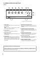
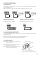
3. NOMENCLATURE AND FUNCTIONS [Front] 5 6 7 8 9 3 MIC TEL PROGRAM AUX MODULE SIGNAL 4 PEAK POWER 2 0 10 0 10 0 10 0 10 0 10 ON OFF 1 INTEGRATED AMPLIFIER BG-1120 This figure represents the BG-1120. 1. Power switch Press to turn ON the power. Press again to turn the power OFF. Note Amplifier operation is enabled about 3 seconds after the power switch is pressed. 5. Microphone input volume control Adjusts the microphone input volume.
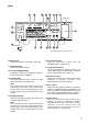
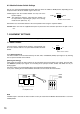
[Rear] 13 14 15 17 19 22 23 24 Blank panel 18 120V 60Hz MAX 500W 12 UNIT BREAKER 4A G COM HOT SENSE OUTLET BREAKER 4A PUSH RESET PROGRAM TEL G – OUTPUT 120 W 120V 60Hz 150W BASS 0 NC UNSWITCHED 11 10 A COM HOT COM 4Ω 25V OUTPUT 1 W 70V 8Ω MOH COM 600Ω COM MODULE MUTE 0 MIC COM HOT G PUSH RESET TREBLE 0 + – PAGE B BGM AUX 27 + MUTE G OUTPUT 1 W 0 PREAMP OUT MOH 10 0 POWER IN 10 CLASS 2 WIRING 10 28 16 20 21 25 26 This figure represents the BG-1120.
20. 1 W output volume control Adjusts the 1 W OUTPUT level. Rotate clockwise to increase and counterclockwise to decrease. 21. MOH output volume control Adjusts the MOH (Music On-Hold) output signal level. Rotate clockwise to increase and counterclockwise to decrease. 22. Mute selector switch Changes the type of mute operation. (Refer to p. 10.) 23. Module selector switch Selects the output terminal for the module signal.
5. OUTPUT CONNECTIONS [Output terminals] Each amplifier has 3 speaker outputs: 4 Ω, 25 V and 70 V. Use only one of these outputs for connection. Class 2 wiring may be used. Note: The impedance in the figure below represents the total impedance of the speaker system. COM 4Ω 25V 70V COM 4Ω 25V 70V 4Ω COM 4Ω 25V 70V 5.2 Ω (BG-1120) 10.4 Ω (BG-1060) 21 Ω (BG-1030) 42 Ω (BG-1015) 40.8 Ω (BG-1120) 81.
6.2. Module Selector Switch Settings Set the rear panel-mounted Module Selector Switch to either the PAGE or BGM position, depending on the output terminal to which the module signal is to be sent. MODULE PAGE: Signals from the installed module are only sent to the speaker outputs. BGM: The terminal to which the signal from the module is to be output differs depending on jumper wire settings inside the unit. (Refer to p. 12.
[Muted signal settings] Use the unit's internal jumper switch JP301 to select the signal to be muted. Select either the input signal from the TEL, MIC, and MODULE (PAGE) terminals or from the AUX, PROGRAM, and MODULE (BGM) terminals as the signal to be muted. Jumper switch JP301 PAGE: TEL, MIC, MODULE ( PAGE) BGM: AUX, PROGRAM, MODULE ( BGM) Note: Selection is factory-preset to the input from AUX, PROGRAM, and MODULE (BGM) terminals. Preamplifier output board 7.1.2.
7.3. AUX, PROGRAM, MODULE (BGM) Output Selection Operations shown in the following table can be enabled with the unit's internal jumper settings.
7.5.2. Program input • Install an optional IT-453A Line Transformer in the specified location on the printed circuit board. • Cut off the JP205 and JP206 jumper wires. T202 JP206 JP205 Preamplifier board T201 Line Transformer IT-453A 8. INSTALLATION Keep the unit's all sides at least 10 cm away from objects that may obstruct air flow to prevent the unit's temperature from rising.
10. CONTROL SETTINGS Output levels are adjustable with individual volume controls. For music play or announcement, adjust the corresponding volume control so that the signal indicator lights intermittently. Note that the sound quality is downgraded when the peak indicator remains lit. To prevent the accidental change of the settings of input volume controls, remove their knobs after setting them to the desired position and attach the volume control covers instead.
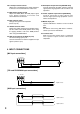
IN OUT AUX –10 dB/47 kΩ Program –10 dB/10 kΩ Module Mute JP201 I.T. Option I.T. I.T. Option EBA Module EBA BGM PAGE AUX Vol. Program Vol. BGM PAGE Tel Vol. Mic Vol. Phantom Power (DC 24 V) 10 kΩ 600 Ω JP204 Tel –20 dB/10 kΩ Mic –60 dB/600 Ω Balanced ON OFF JP213 JP210 JP214 JP211 JP215 JP212 JP209 JP208 JP207 Mute Cont. Mute Cont. P.T MOH Vol. Output 1W Vol. Treble Tone Bass B A Power Mute selector Mute Breaker Power S.W. Power O.T. O.T.
13. SPECIFICATIONS Model No. Power Source Rated Output Power Consumption Rated output Based on UL/CSA standards Frequency Response Total Harmonic Distortion Input Output Output Regulation S/N Ratio Tone Controls Cooling Fan Speed Indicator Protection Other Feature Finish Dimensions Weight (without input module) BG-1015 15 W BG-1030 BG-1060 120 V AC, 60 Hz 30 W 60 W BG-1120 120 W 50 W 40 W 80 W 160 W 260 W 60 W 100 W 150 W 50 – 20,000 Hz 0.