INSTRUCTION MANUAL OUTDOOR COLOR CAMERA C-CV44-3 NTSC C-CV44-3 PAL Thank you for purchasing TOA’s Outdoor Color Camera. Please carefully follow the instructions in this manual in order to ensure long, trouble-free use of your color camera.
TABLE OF CONTENTS 1. SAFETY PRECAUTIONS ................................................................................ 3 2. GENERAL DESCRIPTION ............................................................................. 4 3. HANDLING PRECAUTIONS .......................................................................... 4 4. NOMENCLATURE ............................................................................................. 5 5. INSTALLATION AND CONNECTIONS .........................................
1. SAFETY PRECAUTIONS • Before installation or use, be sure to carefully read all the instructions in this section in order to ensure long, trouble-free operation. • Be sure to follow all the precautionary instructions in this section, which contain important warnings regarding safety. • After reading, keep this manual handy for future reference.
NTSC version complies with Part 15 of the FCC Rules. Note This equipment has been tested and found to comply with the limits for a Class A digital device, pursuant to Part 15 of the FCC Rules. These limits are designed to provide reasonable protection against harmful interference when the equipment is operated in a commercial environment.
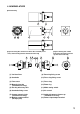
4. NOMENCLATURE [External View] 6 1 7 2 3 4 5 [Figure showing the camera from which the sunshade, front cover, and mounting bracket have been removed] 8 9 10 11 12 13 [Figure showing the camera from which the water-resistant cap has been removed] 15 16 OFF ON F.
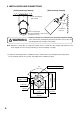
5. INSTALLATION AND CONNECTIONS [Wall mounting example] [Ceiling mounting example] Bracket mounting bolt (M8 or W 3/8) Security wire entry hole Camera mounting bolt Washer-installed M8 x 14mm hex bolt (standard accessory) WARNING Install the unit only in a location that can structurally support the weight of the unit and the mounting bracket. Doing otherwise may result in the unit falling down and causing personal injury. Note: Attach the security wire as required.
[Mounting Example 1] Ceilings or walls [Mounting Example 3] Ceilings or walls Use this method when the camera angle does not need to be adjusted after camera installation is completed. [Mounting Example 2] Walls Use this method when the camera orientation cannot be sufficiently adjusted in Mounting Example 1. Note: If the bracket is only fixed at one place using the bracket mounting bolt, the bracket could rotate or the bolt could become loose.
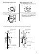
3. Attach the camera to the mounting bracket. Use the supplied insulation spacers, camera mounting bolts (washer-installed M8 x 14mm hex bolt) to attach. Note: Because the induced voltage and noise may be generated at the camera mounts, depending on the installation environment, be sure to use insulation spacers and washers when attaching. Also, never remove the insulation washers attached to the mounting bracket.
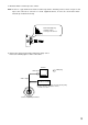
5. Mount the water-resistant cap to the camera. Note: If there is a gap between the water-resistant cap and the mounting surface, water can get in and expose the connector to corrosion. To avoid equipment failures, check to be sure that the waterresistant cap is attached correctly. Fit the watertight cap (shaded section) securely to the camera. 6. Connect the camera to the monitor and power supply source. Refer to the following figure to make connections.
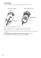
6. ADJUSTMENT 1. Detach the sunshade and front cover after completing camera mounting and connections. [Removing the sunshade] [Removing the front cover] Loosen the two sunshade fixing screws. Turn the front cover in the direction indicated by the arrow to remove. Pull out the sunshade after rotating. Front cover 2. Connect the Monitor output terminal to the monitor. Note: The camera will not operate, even if this terminal is connected to the camera drive. 3.
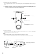
5. Adjust the camera angle. • The camera angle can be adjusted by loosening both the bracket and camera mounting bolts. • To adjust the picture tilt, rotate the shadowed section shown in the figure below so that its projection appears on top. Note: Horizontal camera angles cannot be adjusted in the Example 3 installation described on p. 7. Bracket mounting bolt Focus ring Mode setting switch Horizontal angle ± 60º Projection Zoom ring OFF 1/60 ON F.
9. Insert the sunshade from the front of the camera, as shown in the figure below, and secure it using the sunshade fixing screw (2 places). [Ceiling mounting example] Sunshade fixing screw (washer-installed M3 x 8mm pan head screw) Slot for sunshade fixing screw insertion Sunshade Sunshade fixing screw After inserting, rotate the sunshade clockwise until it stops (as shown in the figure), then secure with the sunshade fixing screws.
7. ABOUT THE MODE SETTING SWITCH Set the Mode Setting switch for the best possible picture reproduction depending on installation conditions. Mode Setting Switch (Factory-preset position) OFF ON OFF Adjustment switch Backlight Compensation switch Shutter Speed switch ON F. ADJ BLC 1/100 SHUTTERR 1/60 IRIS L H (NTSC) 1/60 (PAL) 1/50 1/100 1/120 7.1. Adjustment Switch Set this switch when adjusting the lens focus. (Provides the same effect as when using the ND filter.
8. IF YOU THINK THERE IS A FAILURE: (TROUBLESHOOTING) Symptom Camera images are not displayed on the monitor. Pictures are not clear. Subject under dark lighting conditions goes out of focus. Pictures are too bright. Pictures are curved. The color of the picture periodically varies. Noise appears on the screen. 14 Possible Cause Cables are not correctly connected. The BNC plug is not correctly soldered. Lens is not properly focused. Lens is dirty. Monitor’s image black level is not correctly adjusted.
9. SPECIFICATIONS Model No.
Printed in Vietnam 133-12-875-4F