INSTRUCTION MANUAL VANDAL RESISTANT DAY/NIGHT CAMERA C-CV854D-3 CU C-CV854D-3 CE Thank you for purchasing TOA’s Vandal Resistant Day/Night Camera. Please carefully follow the instructions in this manual in order to ensure long, trouble-free use of your color camera.
TABLE OF CONTENTS 1. SAFETY PRECAUTIONS ............................................................................... 3 2. GENERAL DESCRIPTION ............................................................................. 5 3. HANDLING PRECAUTIONS ........................................................................ 5 4. NOMENCLATURE .............................................................................................. 6 5. INSTALLATION 5.1. Detaching a Dome Cover ...............................
1. SAFETY PRECAUTIONS • Before installation or use, be sure to carefully read all the instructions in this section for correct and safe operation. • Make sure to observe the instructions in this manual as the conventions of safety symbols and messages regarded as very important precautions are included. • We also recommend you keep this instruction manual handy for future reference.
CAUTION Indicates a potentially hazardous situation which, if mishandled, could result in moderate or minor personal injury, and/or property damage. • Leave the installation of the unit to your TOA dealer because the installation requires expert experience and skills. The unit may fall off if incorrectly installed, resulting in possible personal injury. • Do not stand or sit on, nor hang down from the unit as this may cause it to fall down or drop, resulting in personal injury and/or property damage.
2. GENERAL DESCRIPTION The TOA C-CV854D-3 are Vandal Resistant Day/Night Camera equipped with a Day/Night function. It functions as a color camera in the daytime and as a high-sensitivity monochrome camera in darkness, making it ideal for installation in locations that require around-the-clock monitoring. Noise reduction function enables clear image to be viewed in lower noise under poor lighting conditions.
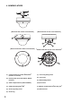
4.
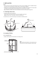
5. INSTALLATION Notes · Do not remove the protective sheet attached to the dome cover until installation work is completed. Damage to the dome cover could result if the protective sheet is removed during installation. · A safety wire for connecting between the unit and ceiling is not supplied. Hook a safety wire for the unit itself to the safety wire-fixing hole (M4, useful thread depth = 6 mm (0.24 inch)) as needed.
2. Connect a coaxial cable to the Video output terminal, and connect the Camera power input cable and power wire from the power-supply unit. 3. Fix the camera unit to the ceiling or wall using the four mounting screws. Attach the supplied base gasket to the camera unit, then install the camera unit to the ceiling or wall. Since no mounting screws are supplied with the camera, prepare them separately depending on the situation. (Use screws that are over 4 mm (0.
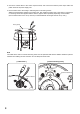
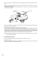
5.2.2. Open wiring from the camera’s side Note The pipe receptacle thread on the camera's side is compatible with 3/4-inch threaded conduit. 1. Loosen the fixing screw with a standard driver, then detach the camera side-attached pipe receptacle thread cover. Fixing screw Pipe receptacle thread cover Cord bush 2. Push in the cord bush attached to the camera unit from the back to pull out from the case. Run the cable and lead it out from the camera pipe receptacle thread hole. Push the cord bush.
3. Attach the removed pipe receptacle thread cover to the threaded section at the upper surface of the camera unit. 4. Wrap two or more layers of sealing tape around the pipe’s threaded section, then screw the pipe into the camera’s threaded receptacle. Sealing tape must be wrapped around the pipe’s threaded part. The pipe to be used must be approximately 100 mm (3.9 inch) in length. Pipe receptacle thread cover Base gasket h) 0 mm rox.10 (3.9 inc App Pipe Sealing tape 5.
6. CONNECTION Note: If the Video output is not terminated at 75Ω, camera images are not properly displayed. Make sure that the output has been terminated at 75Ω at the connected monitor or switcher. The camera power input Use the external power supply unit of the following rating when the camera is operated on 12 V DC. 12 V DC, over 1.
7. ADJUSTMENT 1. Switch on the camera power after completing camera connections. The power is supplied to the camera. 2. Connect the monitor to the Monitor Output terminal to permit a picture to be viewed on the monitor. 3. Set the Flickerless switch to ON if light flicker is annoying. Light flicker may interfere with the view under fluorescent lamps in the area where power frequency is 50 Hz (CU) or 60 Hz (CE).
8. ABOUT THE MODE SETTING SWITCH Set each switch to the position that provides the best picture reproduction. OFF FOCUS ADJUST 1 ON BLC 2 SHUTTER 3 ATW 4 AWB D/N 5 COLOR 1 : Focus adjustment switch 2 : Backlight compensation switch 3 : Flickerless switch 4 : ATW/AWB selection switch 5 : Mode selection switch Mode Setting Switch (Factory-preset setting) 8.1. Focus adjustment switch Set this switch when adjusting the lens focus.
8.4. ATW/AWB selection switch Set the white balance operation. OFF ON 1 2 3 ATW: Set to this position during normal use. The camera's white balance automatically changes as an object's color temperature varies. 4 5 OFF ON 1 2 3 4 5 AWB: Use this switch when the difference between the displayed color and actual color is annoying. Shoot the white object, then turn the switch ON. The camera operates on the initially set white balance even if an object's color temperature changes. 8.5.
10. SPECIFICATIONS Model No.
Printed in Vietnam 133-22-033-70
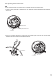
Cautions when Detaching/Attaching an Inner Cover C-CV854D-3 CU C-CV854D-3 CE After detaching the dome cover from the case, do not lift the camera unit by the inner cover. If lifted, the inner cover can be unhooked, and the camera could fall off, possibly resulting in personal injuries or causing damage to the camera. DETACHING AN INNER COVER Detach the inner cover while pushing two of the sections indicated by arrows. Push Inner cover Push ATTACHING THE INNER COVER 1.