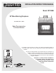
INSTALLATION INSTRUCTIONS MANUAL Model CST38MH 36" Wood Burning Fireplaces P/N 700,033M, REV. C, 12/2006 Retain These Instructions For Future Reference This installation manual will enable you to obtain a safe, efficient and dependable installation of your fireplace system. Please read and understand these instructions before beginning your installation. Do not alter or modify the fireplace or its components under any circumstances.
Table of contents Safety Rules.......................................Page Tools and Building Supplies...............Page Precautions........................................Page Introduction.......................................Page Clearances/Height Requirements.......Page Chimney System................................Page Assembly Outline...............................Page Location of Fireplace..........................Page Assembly Steps.................................Page Preinstallation Notes.........
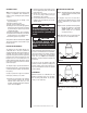
Introduction General Information WARNING The CST38MH Series is a radiant-heat, twosided fireplace with standard glass doors and an outside combustion air kit is provided. A steel grate is also included to properly position the fire and limit the amount of fuel. IF A REPLACEMENT GRATE IS NEEDED REPLACE THE GRATE WITH MODEL SGR-38B ONLY. Note: Illustrations shown reflect “typical” installations with nominal dimensions and are for design and framing reference only.
Note: Local codes may not require firestopping at the ceiling levels for outside chimney enclosure installations. However, it is recommended for safety and the reduction of heat loss. Insulate Joists Same As Ceiling WARNING Draft Stops Do not obstruct the collar openings around the base of the chimney at the top of the fireplace. Do not insulate the chase cavity with blown or fill type insulation materials.
Assembly Steps Note: The following steps represent the normal sequence of installation. Each installation is unique, however, and might require a different sequence. 1. Position firebox prior to framing or into prepared framing. 2. Install the chimney system. 3. Install outside combustion air kit. 4. Plumb gas line if a decorative gas appliance will be used. (Gas connections should only be performed by an experienced, licensed/ certified tradesman). 5. Install both “All-GlassTM” door assemblies. 6.
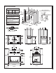
IMPORTANT no combustible materials in shaded areas Under no circumstances can the fireplace top spacers (Figure 13) be removed or modified, nor may you notch the header to fit around or be installed lower than the spacers. The header may be in direct contact with the top spacers but may not be supported by them. Platform metal safety strips " min. (51 mm) Figure 8 Figure 11 4 x 6 header no combustible materials in shaded areas x 4 false header spacer * metal safety strips * * " min.
fireplace specifications Product Reference Information Cat. No. Model Ship. Weight Ship. Volume H4629 CST38MH 237 lb. 29.6 cu. ft. Outside (combustion) Air Kit Required in Manufactured Home Installations 4x4 header Right Side of Fireplace x4 false header (optional) Notes FOAK-6 Outside Air Kit (provided) Due to Lennox' ongoing commitment to quality, all specifications, ratings and dimensions are subject to change without notice.
Framing wall variations As many as six (6) different framed wall configurations can be constructed to enclose the Fireplaces. The following illustrations depict these variations of wall enclosures. Several of these designs may incorporate book shelves, wood storage boxes, etc.
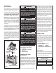
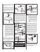
Cut or frame a hole through the outside wall for the installation of the duct inlet hood. A 6 1/2” (151 mm) diameter hole is sufficient. Feed the loose end of the flexible air duct through the hole cut for the inlet hood and attach to collar on inlet hood using the tie strip provided. Insert hood into opening. Secure in place with the No. 8 x 1-1/2” screws provided or with nails driven through holes in hood flange. Seal with noncombustible waterproof silicon type caulking.
For new construction, to determine chimney center line, use plumb line from roof or ceiling above fireplace to center of flue collar on fireplace. Attic Above Outer Pipe Of Chimney 2” Clearance Minimum Thimble Cathedral Ceiling 14" Min. For remodeling, plumb to center of flue collar from ceiling above, drive nail through ceiling from below to mark position, then mark and cut to passage from above ceiling (around nail) (Figure 19).
Step 5. The height of vertical chimney pipe supported only by the fireplace must not exceed 30'. Chimney heights above 30' must be supported by a Model FTF8-S4 stabilizer installed at 30' intervals. locking Tabs (lances) Figure 25 Note: Assemble one component of chimney at a time (inner section first, then outer section last) before proceeding with the next complete section. Note: The Model FTF8-S4 adds 3" net effective height to the total chimney system.
Step 8. The standard Security Chimneys FTF8 roof flashing assemblies include a storm collar. Slide the storm collar over outer chimney, rest on flashing spacers and align with top surface of flashing. Insert tab in slot, pull tight and bend tab back over slot. Seal storm collar to outer chimney with roof caulking or mastic around entire circumference of pipe. Also add extra roof caulking to the tab/slot area to seal completely against water penetration (Figure 30).
3. The effective heights of the components are: Less than 10' (3 m) 2' (610 mm) Min. 3' (914 mm) Min. 10' (3 m) 3' (914 mm) Min. The minimum chimney height above the roof and/or to adjacent walls and buildings is specified by all major building codes. If the horizontal distance from the peak of the roof is less then 10' (3 m), the top of the chimney must be at least 2' (610 mm) above the peak of the roof.
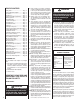
OFfset Elevation Chart A B FTF8-ES30 Number of FTF8 A B Offset Height Offset/Return FTF8-S4 Chimney Sections Offset Height (Inches) fTf8-e30 return elbow* fTf8 chimney sections a fTf8-30 offset elbow* b 48" (1 19 mm) * Part of offset/return Package, model fTf8-es30.
FTF8 Vertical elevation chart Height Of Number Of FTF8 Height Of Chimney Only Chimney Lengths Chimney Only Inches Feet/Inches 12" 18" 11 17 21 27 35 47 51 57 63 67 73 81 93 97 102 109 113 119 127 137 139 143 149 155 159 165 173 183 185 189 195 201 206 212 219 230 231 236 242 248 0 1 1 2 2 3 4 4 5 5 6 6 7 8 8 9 9 9 10 11 11 11 12 12 13 13 14 15 15 15 16 16 17 17 18 19 19 19 20 20 11 5 9 3 11 11 3 9 3 7 1 9 9 1 6 1 5 11 7 5 7 11 5 11 3 9 5 3 5 9 3 9 2 8 3 2 3 8 2 8
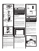
The offset and return elbows may be attached together, or a section or sections of chimney may be used between, but do not exceed 20' (6.1 m) in total length between elbows (Figure 35). If sections of pipe exceed 10' (3 m) between elbows, a chimney stabilizer must be used at the midpoint. The stabilizer support straps must be attached under tension (in shear) to structural framing members above.
Chimney Offset 30° through Floor or Ceiling It may be necessary to assemble the chimney at 30° when passing through the floor or ceiling area. Use the F8FS30-2 firestop spacer as shown in Figures 41 and 42. Support the chimney at floor or ceiling penetration with a FTF8 stabilizer if distance of chimney below ceiling is 10' (3 m) or more. Maintain 2" (51 mm) minimum air space to combustibles from chimney sections. The chimney must pass vertically through the attic space.
If you’re installing a gas line, connect it before the fireplace is framed and enclosed in the finished wall. The gas knockout is determined by a 1-1/8" (29 mm) round indentation located at the bottom and slightly off center in the side refractories. THE KNOCKOUT IS ALWAYS REMOVED FROM INSIDE THE FIREPLACE. DO NOT REMOVE THE KNOCKOUT UNLESS YOU ARE INSTALLING A GAS LINE. If removal is attempted from the outer wrapper, side-refractory damage may occur.
Wall Shield Required Where Less Than 18". Adjacent Wall is Never Allowed Closer Than 8". 40" 40" Hearth Extension Dimensions Protected Side Wall c C D B a 16" B 28-1/2" C 8" D 44-1/2" Note: To convert inches to millimeters divide by .03937.
Calculating Minimum Thickness if Multiple Materials are Used At times it is important to know what combination of materials are acceptable for use as floor protection. The “R values” are used to determine acceptable combinations of materials because “R values” are additive where r and k values are not. “R value” = 1/k = "r" x thickness of material used Example: Given that the required “R value” for a suitable floor protector used must be equal to or greater than: “R” = rL x TL = 1.19 x 1” = 1.19.
installation Components Storm Collar Storm Collar (12 pack) 63L10 FTF8-12 63L13 FTF8-18 H0522 FTF8-24 63L14 FTF8-36 Chimney Section 63L15 FTF8-48 Offset/ Return Package 30 Degree Offset/Return Elbow FTF8-ES30 15 Degree Offset/Return Elbow FTF8-OR15 63L59 FSC 94L77 FSC-B-12 63L22 63L28 Stabilizer Flashing 63L25 FTF8-S4 19M55 F8F6MH 19M56 F8F12MH 63L38 (0-6/12) F8F6 63L39 (6/12-12/12) F8F12 Adjustable Chimney Pipe Kits H0560 FM8-PK20 Ref.
Accessories and Components Ref. Form #750,014M Ref. Form #750,036M Ref. Form #750,077M Arch Type Termination Arch Type Termination 96L22 FTF8-ATT 96L22 FTF8-ATT Chase Termination Chase Termination (Round) 63L45 FTF8-CTDT 96L20 FTF8-CTT Ref.
NOTES NOTE: DIAGRAMS & ILLUSTRATIONS ARE NOT TO SCALE.
The manufacturer reserves the right to make changes at any time, without notice, in design, materials, specifications, prices and also to discontinue colors, styles and products. Consult your local distributor for fireplace code information. Printed in U.S.A. © 2006 by LHP 24 P/N 700,033M REV.