INSTALLATION INSTRUCTIONS CUSTOM SERIES 36" Wood Burning Fireplaces P/N 700,024M REV. N/C 05/2004 MODELS CR-3835R CR-3835L This installation manual will enable you to obtain a safe, efficient and dependable installation of your fireplace system. Please read and understand these instructions before beginning your installation. Do not alter or modify the fireplace or its components under any circumstances.
TABLE OF CONTENTS Safety Rules .................................... page Tools and Building Supplies ............ page Precautions ..................................... page Introduction ..................................... page Clearances/Height Requirements ..... page Chimney System ............................. page Assembly Outline ............................. page Location of Fireplace ....................... page Assembly Steps ............................... page Preinstallation Notes .............
The most important areas of concern dealing with the installation of factory-built fireplaces are clearances to combustible materials, proper assembly of component parts, height of the chimney system, the proper use of accessories supplied by the manufacturer and the techniques employed in using finishing materials applied to the wall surrounding the fireplace, hearth extensions and wall shields. Each of these topics will be covered in thorough detail throughout this manual.
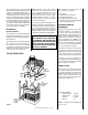
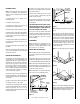
Insulate Joists Same As Ceiling Draft Stops Chimney Height LOCATION OF FIREPLACE The total height of your completed fireplace system from the surface the fireplace rests on to the chimney top must not exceed 50' (15.24 m) and must also meet minimum height requirements. Refer to the minimum system height chart. Carefully select the proper location for heat circulation, aesthetics, chimney obstructions and clearance to side wall(s).
ASSEMBLY STEPS Note: The following steps represent the normal sequence of installation. Each installation is unique, however, and might require a different sequence. 1. Position firebox prior to framing or into prepared framing. 2. Install the chimney system. 3. Connect house wiring to the fireplace for later attachment of optional blower. 4. Install optional outside combustion air kit. 5. Plumb gas line if a decorative gas appliance will be used.
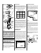
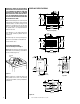
IMPORTANT: UNDER NO CIRCUMSTANCES CAN THE FIREPLACE TOP SPACERS (FIGURE 6 ) BE REMOVED OR MODIFIED, NOR MAY YOU NOTCH THE HEADER TO FIT AROUND OR BE INSTALLED LOWER THAN THE SPACERS. THE HEADER MAY BE IN DIRECT CONTACT WITH THE TOP SPACERS BUT MAY NOT BE SUPPORTED BY THEM. FIREPLACE SPECIFICATIONS 17 1/2" (445mm) 40 1/2" (1029mm) 37 3/8" (949mm) Note: The framed depth, 21 ³⁄₄" (552 mm) from a framed wall, must always be measured from a finished surface.
FRAMING SPECIFICATIONS Back Wall of Chase/Encloslure Including Finishing Materials if any Note: No Wall Shield Required On This Wall E D Rough Framing Face (Unfinished Shown) B C ATO-4 Header A 11 ⁷⁄₈" (302mm) C 8" Max. (203mm) 45° Framing Without False Header 8" (203mm) Min. To Protected Side Wall Figure 12 Note: Combustible Materials May Be Placed In Shaded Area.
Step 6. Route the Class 0 air duct out the back wall or side wall, up through the ceiling or floor joists to an outside wall. The air duct should be located above snow level. Note: If the fireplace is installed against an inside wall, the Class 0 air duct may be extended into a ventilated attic space at least 18" (457 mm) above the attic floor. Secure the duct hood to a vertical post with the inlet positioned downward. Ensure nothing blocks the hood opening.
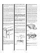
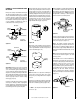
CHIMNEY 30° OFFSET THROUGH FLOOR OR CEILING It may be necessary to assemble the chimney at 30° when passing through the floor or ceiling area. Use the F8FS30-2 firestop spacer as shown in Figures 22 and 23. Support the chimney at floor or ceiling penetration with a FTF8 stabilizer if distance of chimney below ceiling is 10' or more. Maintain 2" minimum air space to combustibles from chimney sections. At all subsequent joints, the upper flue section fits into the preceding flue section.
Note: Do not apply excessive pressure to any subsequent chimney sections following the stabilizer when installing. Ensure each subsequent chimney section is securely attached by testing as noted in Step 4. Note: If chimney extends more than 8' above roof surface, guy wires are also recommended. Use three (3) guy wires, attach to locking band assembly, extend and secure to roof in a triangular pattern (Figure 31 ). Guy wires are not supplied by the manufacturer. Step 6.
FTF8 AND FTF10 CHIMNEY COMPONENT CALCULATIONS Less Than 10' 2' Min. 3' Min 10' 3' Min The minimum installed height of the completed fireplace systems is 15' 2" (4.67 m). The maximum height for all systems is 50' 0" (15.24 m). To determine the number of chimney sections and chimney components required, follow these steps: 1. Determine total vertical height of the fireplace installation.
The offset and return elbows may be attached together, or a section or sections of chimney may be used between, but do not exceed 20' in total length between elbows. If sections of pipe exceed 10' between elbows, a chimney stabilizer must be used at the midpoint (Figure 35 ). The stabilizer support straps must be attached under tension (in shear) to structural framing members above. When two sets of elbows are used, the maximum combined length of chimney used between elbows cannot exceed 20' (Figure 36 ).
FTF8 VERTICAL ELEVATION CHART Height Of Chimney Only Inches 10 16 22 26 32 34 38 44 46 50 56 62 68 72 78 84 90 92 96 102 108 114 119 125 131 137 138 143 149 155 161 165 171 177 183 185 189 195 201 207 211 217 223 229 231 235 241 ¹⁄₄ ¹⁄₄ ¹⁄₄ ¹⁄₂ ¹⁄₂ ¹⁄₄ ¹⁄₂ ¹⁄₂ ¹⁄₄ ¹⁄₂ ¹⁄₂ ¹⁄₂ ¹⁄₂ ³⁄₄ ³⁄₄ ³⁄₄ ³⁄₄ ¹⁄₂ ³⁄₄ ³⁄₄ ³⁄₄ ³⁄₄ ³⁄₄ ¹⁄₄ ¹⁄₄ ¹⁄₄ ¹⁄₄ ¹⁄₄ ¹⁄₄ ¹⁄₄ ¹⁄₄ ¹⁄₂ ¹⁄₂ ¹⁄₂ ¹⁄₂ ¹⁄₄ ¹⁄₂ ¹⁄₂ Number Of FTF8 Chimney Components Feet/Inches 12" 0 1 1 2 2 2 3 3 3 4 4 5 5 6 6 7 7 7 8 8 9 9 9 10 10 11 11 11 12 12 13 13 14
FTF10 VERTICAL ELEVATION CHART Height Of Chimney Only Inches 11 17 21 27 33 35 37 43 51 55 61 67 69 79 85 89 95 103 113 119 123 129 137 147 153 158 164 171 182 188 192 198 206 215 222 226 232 240 250 256 260 266 274 284 290 294 300 308 318 324 328 334 342 352 358 363 369 376 387 393 397 403 411 421 427 431 437 445 455 14 ¹⁄₄ ¹⁄₄ ¹⁄₄ ¹⁄₄ ¹⁄₄ ¹⁄₄ ¹⁄₄ ¹⁄₄ ¹⁄₄ ¹⁄₄ ¹⁄₄ ¹⁄₄ ¹⁄₂ ¹⁄₂ ¹⁄₄ ¹⁄₂ ¹⁄₂ ³⁄₄ ³⁄₄ ¹⁄₂ ³⁄₄ ³⁄₄ ³⁄₄ ³⁄₄ ¹⁄₄ ¹⁄₄ ¹⁄₄ ¹⁄₄ ¹⁄₂ ¹⁄₂ ¹⁄₄ ¹⁄₂ ¹⁄₂ ³⁄₄ ³⁄₄ ¹⁄₂ ³⁄₄ ³⁄₄ ³⁄₄ ³⁄₄ ³⁄₄ ³⁄₄ ³⁄₄ ³⁄₄ ¹⁄₄ ¹⁄₄ ¹⁄
FTF8 OFFSET ELEVATION CHART (With FTF8-SS Starter Section) A Offset B Height (Inches) (Inches) 14 19 22 24 27 30 31 32 35 36 37 38 39 41 42 44 45 47 48 49 51 53 54 55 56 58 59 60 61 65 66 68 69 71 74 77 78 80 83 84 89 89 92 92 ¹⁄₄ ¹⁄₄ ¹⁄₄ ¹⁄₄ ¹⁄₄ ¹⁄₄ ¹⁄₄ ¹⁄₄ ¹⁄₂ ¹⁄₄ ¹⁄₄ ¹⁄₄ ¹⁄₄ ¹⁄₄ ¹⁄₄ ¹⁄₂ ¹⁄₄ ¹⁄₄ ¹⁄₂ ¹⁄₄ ¹⁄₄ ¹⁄₄ ¹⁄₄ ¹⁄₄ ³⁄₄ ³⁄₄ ³⁄₄ ³⁄₄ ³⁄₄ ³⁄₄ ³⁄₄ ³⁄₄ ³⁄₄ 32 41 46 50 55 60 62 64 69 71 72 74 76 79 81 85 86 90 91 93 97 100 102 104 105 109 111 112 114 122 124 126 129 132 138 141 144 146 152 155 162 164
FTF10 OFFSET ELEVATION CHART B Height FTF10-ES30 Offset/Return FTF10-S4 Number of FTF10 Chimney Sections (Inches) (Inches) Elbow Set Stabilizer 12" 18" 36" 1 1 1 1 1 1 1 1 1 1 1 1 1 1 1 1 1 1 1 1 1 1 1 1 1 1 1 1 1 1 1 1 1 1 1 1 1 1 1 1 1 1 0 0 0 0 0 0 0 0 0 0 0 0 0 0 0 0 0 0 0 0 0 0 0 0 0 0 0 0 0 0 0 1 1 1 1 1 1 1 1 1 1 1 0 1 0 2 1 0 0 2 1 1 0 0 2 4 1 3 0 0 2 1 1 3 0 0 2 1 1 0 0 2 1 1 0 2 1 1 0 2 1 3 0 1 0 0 1 0 1 2 0 1 2 0 3 1 0 1 1 0 2 0 1 4 0 1 3 1 0 5 1 2 0 1 2 0 1 0 3 1 2 1 0 1 1 1 0 0 0
INSTALLING OFFSETS First, review the Offset Elevation Chart and Figure 39 for reference. Step 1. Determine the offset distance where chimney is to pass through the first ceilingdimension “A.” To find this point on your ceiling, first determine the center point for a vertical chimney following the instructions for vertical installation. Measure height to the ceiling from the top of fireplace-dimension “B.” Use the appropriate Offset Elevation Chart to find dimension “A.
Glass Doors If glass doors are to be installed on these fireplaces, refer to specific installation instructions packed with the glass doors. Use only the doors that are listed for use with these fireplaces. Use of other non-listed glass door on these fireplaces may constitute a potential fire hazard and is not recommended. CAUTION: CERTAIN GLASS DOORS OVERLAP THE BLACK METAL FACING OF THE FIREPLACE.
Methods of Determining Hearth Extension and Wall Shield Equivalents “R value” = 1 = r x thickness of material used k To determine the thickness required for any material when either the k or r values are known: Alternative Hearth Extension Materials TM kM rM TL = = = = Thickness of material in inches K value of desired material R value of desired material Minimum listed thickness Example: Micore CV230 is to be used for the hearth extension fireplace.
FINISH TO YOUR TASTE INSTALLATION COMPONENTS There are a wide variety of “finished looks” for these fireplaces, from formal wall decor with elaborate mantels to rustic wood paneling or warm brick facings. The following items are available for use in the installation of this appliance. Only noncombustible materials like stone, tile, brick, etc., may overlap the black front facing. Do not extend these materials beyond the black facing and into the firebox area.
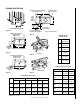
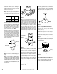
INSTALLATION COMPONENTS Chase Termination (Square) 63L51 63L52 Firestop Spacer (Flat) FTF8-CT2 FTF10-CT2 Cold Climate Kit Chase Termination (Round) 63L45 63L46 63L63 FTF10-CCK1-LD Stabilizer 63L25 63L26 FTF8-S4 FTF10-S4 FOAK FOAK-LD Spark Arrester 63L57 FSA-2 FTF8-C P7 SUPERI OR CHIMNE ASSEM Y BLY 96L20 96L21 FTF8-CP7 OR SUPERI BLY Y ASSEM CHIMNE Round Termination 63L42 63L43 FTF8-CTD FTF10-CTD RIOR Chimney Pack Conventional FTF10CP SUPERI 8 OR CHIMNE ASSEM Y BLY 96L22 96L23 Conta
NOTE: DIAGRAMS & ILLUSTRATIONS NOT TO SCALE.
NOTE: DIAGRAMS & ILLUSTRATIONS NOT TO SCALE.
The manufacturer reserves the right to make changes at any time, without notice, in design, materials, specifications, prices and also to discontinue colors, styles and products. Consult your local distributor for fireplace code information. Printed in U.S.A. © 2004 by LENNOX HEARTH PRODUCTS 24 P/N 700,024M REV. N/C 05/2004 NOTE: DIAGRAMS & ILLUSTRATIONS NOT TO SCALE.