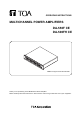
OPERATING INSTRUCTIONS MULTICHANNEL POWER AMPLIFIERS DA-550F CE DA-500FH CE Note: The figure shows the DA-550F. Thank you for purchasing TOA's Multichannel Power Amplifier. Please carefully follow the instructions in this manual to ensure long, trouble-free use of your equipment.
TABLE OF CONTENTS 1. SAFETY PRECAUTIONS ............................................................................... 3 2. GENERAL DESCRIPTION ............................................................................. 4 3. FEATURES .......................................................................................................... 4 4. HANDLING PRECAUTIONS .......................................................................... 5 5. INSTALLATION PRECAUTIONS .....................................
1. SAFETY PRECAUTIONS • Before installation or use, be sure to carefully read all the instructions in this section for correct and safe operation. • Be sure to follow all the precautionary instructions in this section, which contain important warnings and/or cautions regarding safety. • After reading, keep this manual handy for future reference.
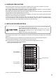
• The unit is designed exclusively to be mounted in an equipment rack. Be sure to follow the instructions below when rack-mounting the unit. Failure to do so may cause a fire or personal injury. · Install the equipment rack on a stable, hard floor. Fix it with anchor bolts or take other arrangements to prevent it from falling down. · The supplied rack-mounting screws can be used for the TOA equipment rack only. Do not use them for other racks.
4. HANDLING PRECAUTIONS • Keep the input cable away from the output cable. If installed close to each other, oscillation could occur. • To avoid unit failures, never connect outputs of 2 or more units in parallel. • Only connect speakers with an impedance equal to or greater than those specified. Connecting speakers with a smaller than specified impedance could cause damage to the unit. • Periodically clean the filter located inside the ventilation panel on the unit's front panel.
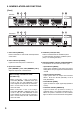
. NOMENCLATURE AND FUNCTIONS [Front] DA-550F DA-500FH 3 4 5 2 1 3 4 5 2 1 1. Power switch [ON/OFF] Power is switched on and off with each depression of this switch. 2. Power indicator [POWER] Lights blue when the power is switched on. 3. Input level controls [CH 1 (BRIDGE 1), CH 2, CH 3 (BRIDGE 2), CH 4] Adjust the input level of each channel.
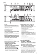
[Rear] 6 7 8 9 9 6 7 8 9 9 10 11 10 DA-550F 12 11 DA-500FH 12 6. AC inlet Connect the supplied power cord to this inlet. The socket-outlet shall be installed near the equipment and the plug (disconnecting device) shall be easily accessible. 7. Control/Monitor terminals [CONTROL/MONITOR] Connecting external equipment to these terminals makes the control and monitor functions available for channels 1 – 4 individually. (See p.15; How to Use the Control/Monitor Terminals.) 8.
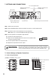
7. SETTINGS AND CONNECTIONS CH 1 mode ON/OFF switch BRIDGE 2 ON/OFF switch (DA-550F only) BRIDGE 1 ON/OFF switch (DA-550F only) [Rear panel] Note: The figure shows the DA-550F. Input terminals Speaker output terminals (with a terminal cover) Step 1. Switch off the unit's power. Step 2. Set the BRIDGE ON/OFF switches (DA-550F only) and CH 1 mode ON/OFF switch. Step 3. Connect the sound source equipment to the Input terminals. Note: Refer to p. 11 for the removable terminal plug connection. Step 4.
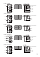
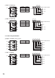
[1 input - 4 outputs] CH1 CH1 CH2 Switch Setting BRIDGE 1 OFF BRIDGE 2 OFF CH 1 mode ON CH4 CH3 CH2 CH1 - - - - + + + + Speaker output terminals 4–8Ω CH3 4–8Ω CH4 4–8Ω 4–8Ω [2 inputs - 2 outputs] CH1 CH1 CH2 Switch Setting BRIDGE 1 ON BRIDGE 2 ON CH 1 mode OFF Speaker output terminals BRIDGE 2 - + - + BRIDGE 1 8Ω CH3 CH3 8Ω CH4 [1 input - 2 outputs] CH1 CH1 CH2 Switch Setting BRIDGE 1 ON BRIDGE 2 ON CH 1 mode ON Speaker output terminals BRIDGE 2 - + - +
[1 input - 3 outputs (1)] Switch Setting BRIDGE 1 OFF BRIDGE 2 ON CH 1 mode ON CH1 CH1 CH2 CH2 CH1 - - + + Speaker output terminals BRIDGE 2 - + 4–8Ω 4–8Ω CH3 8Ω CH4 [1 input - 3 outputs (2)] Switch CH1 CH1 CH2 CH4 CH3 - - + + Setting BRIDGE 1 ON BRIDGE 2 OFF CH 1 mode ON Speaker output terminals - + BRIDGE 1 8Ω CH3 4–8Ω CH4 4–8Ω 7.1.2.
8. REMOVABLE TERMINAL PLUG CONNECTION Cautions • Be sure to use shielded cables for audio signal lines. • Avoid soldering cable conductor, as contact resistance may increase when the cable is tightened and the solder is crushed, possibly resulting in an excessive rise in joint temperatures. • Use cables of AWG 12 – 24. Cable end treatment Shielded cable 7 mm 20 mm Connector connections Step 1. Loosen the terminal screw, then insert the cable. Step 2. Retighten the terminal screw.
9. INPUT SENSITIVITY SETTING The input sensitivity for each channel can be set to either +4 dB (factory preset) or –10 dB. CAUTION These servicing instructions are for use by qualified personnel only. To avoid electric shock, do not perform any servicing other than that contained in the operating instructions unless you are qualified to do so. Refer all servicing to qualified service personnel. Step 1. Unscrew 9 screws securing the top cover of the unit, then detach it. Step 3.
11. TAMPER-PROOF CAP ATTACHMENT To protect the input level control from accidental operation, it is recommended to replace the control knob with the supplied tamper-proof cap as illustrated. Input level control Tamper-proof cap (accessory) 12. CLEANING THE FILTER Step 1. Switch off the unit's power. Step 2. Remove the ventilation panel as shown in the figure. Step 3. Detach the filter inside the ventilation panel. Step 4. Clear the filter of dust. Step 5. Replace the filter and ventilation panel.
. BLOCK DIAGRAMS 14.1.
. HOW TO USE THE CONTROL/MONITOR TERMINALS The Control/Monitor terminals on the rear panel permit power ON/OFF control of the individual channels and monitoring for the power ON/OFF status and protection status on each channel, and fan operation status. Prepare the control panel and status monitor display panel separately referring to the descriptions below. Notes • All terminals are electrically isolated from the unit body with the photocouplers.
15.3. About Pin 7 of the Control/Monitor Terminals A ground common to all the control and monitor terminals is assigned to Pin 7. Both Pins 7 of the Control/Monitor terminal for CH1 and CH2, and that for CH 3 and CH4 are internally connected to each other. Pins 7 are isolated from the unit body. 15.4. Terminal Pin Arrangement Unit operation status Terminal Pin No.
15.6. RJ45 Connector's Pin Arrangement and Cable Color Codes To Control/Monitor terminal RJ45 pin No. Cable color (for T568B) Cable color (for T568A) RJ45 pin No.
16. SPECIFICATIONS 16.1. DA-550F CE Power Source Amplification system Power Consumption Input Rated Output Frequency Response Total Harmonic Distortion Protection circuit S/N Ratio Crosstalk Control/Monitor LED Indicator Cooling Operating Temperature Operating Humidity Finish Dimensions Weight 220 – 240 V AC, 50/60 Hz Digital class D 480 W (based on EN standards), 2750 W (rated output 4 Ω x 4), 1550 W (rated output 8 Ω x 4) 4 circuits, +4 dB* (1.
16.2. DA-500FH CE Power Source Amplification system Power Consumption Input Rated Output Frequency Response Total Harmonic Distortion Protection circuit S/N Ratio Crosstalk Control/Monitor LED Indicator Cooling Operating Temperature Operating Humidity Finish Dimensions Weight 220 – 240 V AC, 50/60 Hz Digital class D 460 W (based on EN standards), 2350 W (rated output 20 Ω x 4) 4 circuits, +4 dB* (1.
Traceability Information for Europe (EMC directive 2004/108/EC) Manufacturer: TOA Corporation 7-2-1, Minatojima Nakamachi, Chuo-ku, Kobe, Hyogo, Japan Authorized representative: TOA Electronics Europe GmbH Suederstrasse 282, 20537 Hamburg, Germany URL: http://www.toa.