TOA EX-16 INTERCOM SYSTEM INSTALLATION HAND BOOK TOA ELECTRIC CO., LTD.
1. Introduction . . . . . . . . . . . . . . . . . . . . . . . . . . . . . . . . . . . . . . . . . . . . . . . . . . . . . . 2. Introduction of the EX-16 S y s t e m . . . . . . . . . . . . . . . . . . . . . . . . . . . . . . . 2.1 E x c h a n g e . . . . . . . . . . . . . . . . . . . . . . . . . . . . . . . . . . . . . . . . . . . . . . . . 2.1.1 Features 2.1.2 Specifications 2.1.3 Further Details 2.1.4 System Block Diagram 2.2 S t a t i o n s . . . . . . . . . . . . . . . . . . . . . . . . . . . . . . . .
1. Introduction This is the installation manual for the exchange, stations and other components of TOA Intercom System EX-16. It includes an outline of the system, an explanation of installation, cable connection, inspection procedures and a troubleshooting guide. Careful study of this manual is recommended prior to installation of the system. This manual is only intended to give the information necessary for proper installation of the system.
2.1.2 Specifications The exchange is available with the following specifications. EX-16 Capacity: Dimensions: 16 lines max. (with paging function) 360(W) X 300(H) X 100(D)mm (14.2" X 11.8" X 3.9") Weight: 8.3 kg (18.3 lbs.) with 16 lines Exchange capacity can be increased within the given limits in units of 4 lines.
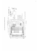
Terminal for Station Mother Board Connector — Power Supply Module (DSM-16) AC/DC Input Terminal Power Switch Voltage Selector Power Indicator DC Fuse Holder AC Fuse Holder Terminal n EX-16 DIMENSIONS in mm Power Transformer Short Bar Central Processing Unit (CPU-16) Line Amp Unit (LAU-16) (a) Structure of Exchange and Names of Parts 3
(b) CPU (Central Processing Unit) The Central Processing Unit is divided into two sections: common control and speech path. Common control: This section consists of a microcomputer and associated other circuits. It controls receiving dial data from stations, opening and closing of speech path, controlling of signal, paging and BGM switches in accordance with the exchange program.
(c) LAU (Line Amplifier Unit) The Line Amplifier Unit consists of a power supply circuit for stations, transmitting and receiving circuits for voice signal, speech path switches, BGM switches and the dial data receiving circuits. One unit accepts up to 4 stations. A maximum of 4 LAU's can be installed.
(e) Integral Terminal for Connecting Stations The connection terminal for the exchange and stations is built into the exchange and connected to each LAU with a mother board. (Wiring of the terminal and the station will be explained in a separate section.) 2.1.4 System Block Diagram A block diagram of the EX-16 system is shown below. In a standard system, at least one LAU-16 is installed. The remaining units are optional. Each LAU-16 contains the necessary circuitry for four stations.
2.2 Stations 2.2.1 Features The stations used in the Toa Intercom EX-16 have the following features: 1. Each station is provided with a male 4-pin plug (YC-102) for easy con- nection to cables. 2. Wiring from the exchange to each station is an independent 4-wire system. The fact that only 4 wires are necessary makes installation easier, and with a 4-pin jack (YC-101 or YC-103) at the end of each cable, connection can be made quickly with only a screwdriver.
Station Specifications Permissible Loop Resistance: 300 ohms Input/Output Impedance: 600 ohms (balanced) Loudspeaker Output: 300mW maximum Handset Speaker Output: 100mW maximum 2.3. Accessories 2.3.1 Wall Mounting Panel (YC-100) The wall mounting panel is used for HFM-100 and HFS-100 when these stations are to be surface wall-mounted. 2.3.2 Talk-Back Unit (TKU-11) This unit, optional amplifier (10W max.) and speaker (Hi-Z) will allow highvolume paging with response from speaker.
1. Power Switch Power Indicator 3. Output Volume Control 4. Input Volume Control 5. Rubber Foot 6. AC Inlet 7. Voltage Selector 8. 8-Pin Terminal Board 9. Output Jack 10. Terminal Board Cover 2. SPECIFICATIONS Power Source: 100~120/200~240V AC Input: Talk-Back Max. 30 dBm, Amplifier Max. 10W, Hi-Z Output: Talk-Back Max.
3. Installation of the EX-16 System 3.1 Precautions for Installation 3.1.1 Exchange Pay particular attention to the following points: * The layout should allow easy servicing and inspection. * The exchange is compact and lightweight; however, it is important to ascertain the strength of the wall on which it will be placed. * The exchange should be grounded.
3.1.2 Stations Particular attention should be given to the following points during installation. * A desk-type, wall-mounting-type or desk/wall-type should be chosen according to the user's need. * If the all-call paging or talk-back function is adopted, precautions should be taken to ensure against feedback due to interference between the station (microphone) and the paging or talk-back speaker; that is, they should be installed facing different directions or separated as far as possible from each other.
3.2 Cable Installation Wire type, number of wire pairs and number of individual wires are to be determined for individual sections of the wiring system according to the guidelines set down below. * 4-wire twisted pair cables are to be used for wiring between indoor terminal boards, intermediate terminal boards, main terminal boards, etc. * Outdoor wires should be used where wiring passes through inaccessible areas such as in ceilings or under floors.
3.4 Wiring General Information * Wiring should be done independent of public telephone lines. * The wiring conduit is often installed underground or embedded in building structures such as walls and floors, so care should be taken to draw up a wiring plan that has ample reserve for future extension of the system and that can be adapted to future remodelling or expansion of the building it is housed in.
3.5 Piping * Where wiring is to be passed through a wall or the like, it should be protected by a hard PVC or metal tube. * If the number of connecting wires between an indoor terminal board and a station is small and the station's site is fixed so that it will not be moved frequently, install a box at that site and pull wiring through a metal or hard PVC tube as required by job or ordinance. * Use a floor duct if the number of connecting wires is large and the stations are likely to be moved frequently.
3.6 Connection between the station and the exchange Station 4-Pin Plug (YC-102) Plug in (Cover) 4-Pin Jack (YC-101) (YC-103: 4-Pin Jack for flush-mount) NOTE: Use 4" X 2" Switch Box for YC-103.
Clipping Tool C (YC-105) Note: Connect the individual cables in order, starting with the top terminal. When using the clipping tool, be sure that the cutting edge is on the side of the wire to be cut off.
TERMINAL BOARD EX-16 WIRING INSTRUCTIONS 1 STATION CONNECTIONS or 2 TALK-BACK CONNECTIONS TKU-11 TERMINAL SPEAKER LINE INPUT 17
3.7 AC/DC Power Supply Connection A 5P terminal for AC and DC power supply is provided on the DSM-16. The power cable, YA-308 or YA-309, can be connected to the 5P terminal. Be sure to ground the exchange. Power Supply Cables 5P Terminal on DSM-16 YA-308 YA-309 3.8 Connection of the Input/Output Terminal A 6P terminal for the input/output signals of the EX-16 is provided on the DSM-16.
3.8.1 BGM Input Input impedance: 50 K (a) (unbalanced) Input level: -10dB max. Output level: 100mW Remove the short bar connected to the terminal. (When BGM is not employed, the short bar should be kept on the terminal. If the short bar is not replaced, a humming sound will be heard from the station.) The short bar is referred to on page 3. (b) Connect the BGM equipment. (Be sure to use the type of BGM equipment which meets the input specifications.
3.8.
3.9 Connection of the Talk-Back Unit Connection of the talk-back unit is shown below. SPEAKER SPEAKER EX-16 TERMINAL BOARD TKU-11 Fig. 14 When the talk-back speaker is used as a microphone, sound clearness and microphone sensitivity vary according to the ambient noise level and installation position. The sensitivity of the talk-back speaker's microphone can be adjusted by the input volume control on the front of the TKU-11. Adjustment is necessary after installation.
3.10 Connection of the Speaker Station In the EX-16, instead of using a station, a speaker for one-way conversation can be installed using a jumper in the LAU-16. This is possible at each station position on the LAU-16. 3.10.1 Wiring Procedure (a) First, determine the number of station speakers to be installed. (Any number of station speakers may be connected within the limits of the station numbers from No. 2 to No. 17.) (b) Use the Wiring Instruction Chart to determine the LAU No. and Jumper No.
3.10.3 Connection with the Exchange Connect speakers to terminals 1 and 2 as shown in the diagram. (Leave terminals 3 and 4 open.) 3.10.4 On/Off Control of BGM BGM can be turned off when the jumpers are connected as shown in the diagram. If the jumpers are not connected, BGM will be heard from the speaker stations constantly. (See page 24.
Jumper for Speaker Station Selection Jumper for BGM On/Off For BGM on/off operation remotely, the control line can be extended the same way as for station wiring. How to Connect the Jumper Wire 1. Use a 0.6mm diameter plated wire as jumper. 2. Solder on the soldered end. 3. Use a soldering iron with less than 30W power and with minimum leakage. Be careful not to touch other parts.
4. Installation Adjustment 4.1 Inspect Before Turning Power On. * Before supply power, check the power connections (power connections should be complete) and the fuse. Also, voltage selector should be set correctly. All modules should be in place. Check the ROM on the CPU-16. It should be set securely in the socket. Make sure that exchange and stations are properly connected. * Turn power on. * AC indicator lamp on the DSM-16 should go on. If not, electricity is not on.
Program Switch Details Power Remote Door Remote 1. Set the mini-jump in the JP1 position for door remote. Relay goes on for 4 seconds when buttons and are pressed. 2. Set the mini-jump in the JP2 position for power remote. Press buttons and Press button to turn relay off. Note: to turn relay on. The unit is set in the JP1 position (door remote) at the factory. 4.3 Testing After: 1. wiring is completed 2.
4.3.1 Precedure (1) Turn on power switch on the exchange. (2) Adjust the sound level of the external PA paging and check the power remote function. (a) Connect one station. (b) Press buttons and to test the sound level. Adjust the volume control of the external amplifier. (3) Complete a speech test with each of the other stations. (a) Connect the plug for the station to be tested. (b) Dial the station number. Check the sound level and the speech quality. (c) Dial and .
(3) If the voltage measured is normal at every point, connect one unit at a time checking the voltage after each connection. (4) If the voltage is upset after connecting any given unit, the unit is to be replaced. (b) If there is no response to dialing: (1) Disconnect the plug for the particular station from the line and check the wiring between the exchange and the station. (2) If no wiring error is detected, test after changing each station.
4.3.3 Relationship Between Ambient Noise and Conversation Mode The EX-16 system is provided with voice switches for the press-to-talk function which is required when the ambient noise level is high. Below is a guide for using the press-to-talk function. (Up to 60 phons) (A) (Up to 60 phons) (A) (Up to 60 phons) (B) (Hands free) (Hands free) (Above 60 phons) (B) (Hands free) (Press-to-talk) 5.
5.1 Fault in Exchange * When the power supply unit or the CPU-16 is out of order, the same kind of fault will occur at all stations. * When the LAU-16 is out of order, a fault will appear only at a particular station. * If the exchange is out of order, the faulty unit must be searched out and replaced. Fault in exchange Fault Check the power unit (See 4.3.
5.2 Fault in Specific Station Only Find the cause according to the following table if the fault lies with a specific station only, not with all stations. SYMPTOM CHECK-ITEM CAUSE Dialing can not be made at privacy off mode. * Disconnection of both T & R Lines. Replace the station and make * T & R Lines are shorted. sure that the station is not faulty. Specific key does not operate. * Fault in key board switch or matrix circuitry. Replace the station and make * Fault in the dial generator.
5.3 Fault in Cable 1. One of transmitting lines (T-Line) is disconnected Disconnected Station (B) T-Line Station (A) T-Line R-Line R-Line EXCHANGE Symptom: Connector numbers 1-1 A can dial. 1-2 A can hear B. 1-3 B can not hear A. 1-4 Noise is heard at B. 1-5 Noise increases at B when Press-To-Talk bar is pressed at A. 2. One of receiving lines (R-Line) is disconnected. (B) R-Line R-Line EXCHANGE Symptom: (A) T-Line T-Line Disconnected 2-1 A can dial without dialing tone.
3. T-Line and R-Line are shorted or mixed up. Shorted or mixed up T-Line (B) (A) T-Line R-Line R-Line EXCHANGE Symptom: 3-1 A can not dial. 3-2 Conversation is impossible between stations. 3-3 When B dials A, noise will be heard at B immediately after the calling tone. 4. T-Line and R-Line are connected conversely. T-Line (B) T-Line R-Line R-Line EXCHANGE Symptom: (A) Conversed 4-1 A can not dial. 4-2 Conversation is impossible between stations.
TOA ELECTRIC CO., LTD.