EXES-6000 CP-63 For INTERCOM SYSTEM TOA EXES-6OOO INTERCOM SYSTEM Central Processing Unit for Tie-line System CP-63 INSTALLATION HAND BOOK TOA ELECTRIC CO., LTD.
CONTENTS Page 2 3 5 8 INTRODUCTION TO THE INSTALLATION MANUAL FOR EXES-6000 FUNCTIONS WHICH REQUIRE ADDITIONAL UNITS TIE-LINE CONNECTION OF THE EXCHANGES WIRING FOR TIE-LINE CONNECTION OF THE EXCHANGES PART 1. OPERATING OF CP UNIT AND NO. 200 PROGRAMMING 1. 2. 3. 4. 5. 6. 7. Precautions for Installation of CP-63 Initial CP 63 set up Trouble Shooting CP-63 DIP Switches for Function Selection Dip Switch Selection and Station No. 200 Programming for Each Function Function Code Table for Station No.
INTRODUCTION TO THE INSTALLATION MANUAL FOR EXES-6000 This manual forms part of the Installation Manual for TOA INTERCOM SYSTEM EXES-6000. You may add the CP-63 to your TOA INTERCOM SYSTEM EXES6000, according to your specific needs, to obtain various other functions. Correct operation of these additional functions is not performed by simply connecting the additional equipments/devices. Provision of such additional function requires the following: (1) Connection of the additional equipment, as required.
FUNCTIONS WHICH REQUIRE ADDITIONAL UNITS Those functions of the CP-63 which require either the addition of specific units or processing in existing units are as mentioned below. Before installation and adjustment of equipment, make sure to check your system. (For Data Transmitting and Receiving units, refer to Part 2. "Function Selection for Data Transmitting and Receiving units" Page 49.
Example of Exchange Mounted on Intercom Cabinet Rack (For Tie-line System Including All-Call Paging and 7 Individual Zone Paging unit and one Data Transmitting unit) Exchange EX-620 (for 128 stations) Exchange EX-610 (for 64 stations) Central Processing Unit CP-63 Power Supply Unit DS-620 Output Control Unit OC-62 Power Switch Highway Control Unit HC-62 AC Fuse Signal Generating and Distributing Unit SG-62 DC Fuse Conference Link Unit CL-62 (In this location, DL-62 is also mountable.
TIE-LINE CONNECTION OF THE EXCHANGES 1. Function of the Central Processing Unit CP-63 Exchange "A" To make communications between exchanges possible in the EXES6000 system, the CP-63 and the Tie-line Interface Unit TI-62 are required in addition to the exchange EX-610 or the EX-620. The TI-62 is the interface unit for transmitting and receiving audio signals and dial data signals between the exchanges.
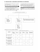
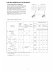
3. Numbering schedule for stations and paging zones A. With personal number (Standard) Numbering for stations Type of Model exchange With paging Without Paging Numbering for paging zones 7 zones per exchange Paging zone per exchange All call Zone EX-610 Single Exchange (EX-1) Exchange "A" (EX-2A/3A) EX-620 EX-610 Exchange "B" (EX-2B/3B) EX-620 EX-610 Exchange "C" (EX-3C) EX-620 B.
6. The relationship between the PI unit and the LM unit Exchange "A" The case where it is necessary to make the paging call from the exchange without the PI unit to the other exchange (s). Set "Paging" DIP switch (SW-B-4) to ON. You may not substitute the LM unit (LM8 or LM16) for the PI unit. EX-610: Max. 48 stations, EX-620: Max.
WIRING FOR TIE-LINE CONNECTION OF THE EXCHANGES Each exchange can be connected by means of a cable with a diameter of 0.65mm (25.6 mils.) for a distance of up to 2km (5600 ft). Regarding the tieline links which are not used, turn off the DIP switch of each unused tieline link inside the Tie-line Unit TI-62. Connect "T" line (2 wires) of the 4 wires of each link to "R" line (2 wires) of the other exchange. The 2 wires of the "T" line and "R" line have no polarity. If the BX-610/620 is used, its terminals No.
4.
5.
PART 1. OPERATING OF CP UNIT AND NO. 200 PROGRAMMING 1. PRECAUTIONS FOR INSTALLATION OF CP-63 Please read following instructions carefully to ensure proper operation of the CP-63 1. Be careful about damage by static electricity as the CP-63 incorporates CMOS IC's. Do not touch components and connectors. 2. Turn off the AC power switch when you take out or insert the CP-63 unit, or any other unit. 3. Always insert the CP-63 unit into the "CP" slot. Otherwise, there is a danger that the unit will be damaged.
2. INITIAL CP-63 SET UP In the event of the tie-line system, programming has to be set up in every exchange. Make sure that you have turned off the AC power switch. Connect the exchange, terminal boards and stations. Are Data Transmitting and Receiving Units used? 1. Connect Data Transmitting Unit (DTE11) and Data Receiving Unit (DRB61). 2. Set channel select switches (CHANNEL SELECT) of DT-E11. 3. Set word select switches (WORD SELECT) of DR-B61. Remove CP-63 from the exchange.
3. TROUBLE SHOOTING Error ROM • RAM Chip No. 3-1 Check of ROM & NMOS-RAM - No calls on the system. 1. Put the 4 "LINK SELECT" switches of the HC upward (Link No. 15 SELECT) and switch on the AC power of the exchange. 2. If there is no error, the indication lamps will not light. 3. In the event of a memory error, the lamps may light as shown in the example of Fig. 1. 4. The error indications will remain on until you use Link No. 15 for communications. Example No. 1 and No.
3-6 The order of Tie-line link usage The Tie-line Link Number which is used in calls between exchanges is not directly indicated, but you can possibly get it from the link number which is indicated on the HC-62. When one Tie-line Link brings up some problems which cause the system not to work properly, try to find which link number is causing the problems from the indication on the HC-62 of the exchange making the call. As Fig. 1 and Fig.
Reference for Connection Link Number between DL and Tl Link Exchange which is called Exchange which calls Tl Tie-line Link Number DL Link No 2 Tie-lines Tl Tie-line Link Number Tie-line Link Fixed by Connection Cable between Exchanges After power switch is on, Links are used in numerical order 3 Tie-lines Note. If the Tl Tie-line Link which corresponds with the DL Link No. is already busy, then, the next Tie-line Link is automatically used.
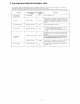
4. CP-63 DIP SWITCHES FOR FUNCTION SELECTION Functions SW-A SW-B Switch ON Switch OFF Link Selection; Link No. 0 ~ 3 Not Activate Activate Link Selection; Link No. 4 ~ 7 Not Activate Activate Link Selection; Link No. 8 ~ 1 1 Not Activate Activate Link Selection; Link No.
5. DIP SWITCH SELECTION AND STATION NO. 200 PROGRAMMING FOR EACH FUNCTION No. 200 Programming should be proceeded in the following manner. 1. Write down the required data in "8. Programming Data Table (Page 42 ~ 47)". 2. Carry out the registration according to "6. Function Code Table for Station No. 200 Programming (Page 18 ~ 20)" and "7. Station No. 200 Programming for Each Function (Page 21 ~ 40)". Registration or Operation at Each Station No.
6. FUNCTION CODE TABLE FOR STATION NO. 200 PROGRAMMING A.
FUNCTION CODE TABLE FOR STATION NO. 200 PROGRAMMING B. Programming of System Function Group Function Function Code Remarks Initially Programmed Mode Operating for Programming The following standard station numbering schedules of the exchanges A, B and C are obtainable.
FUNCTION CODE TABLE FOR STATION NO. 200 PROGRAMMING C. Programming of each Function Function Group A B C Function Function Code 1st Parameter Executive Priority 50 Station No. ON/OFF (1/0) Continuous Calling Tone 51 Station No. ON/OFF (1/0) Station Allowed Access to All Call 52 Station No. ON/OFF (1/0) 53 Station No. ON/OFF (1/0) 54 Station No. ON/OFF (1/0) 56 Station No. ON/OFF (1/0) 57 Station No.
7. STATION NO. 200 PROGRAMMING FOR EACH FUNCTION 7-1 EXECUTIVE PRIORITY (FUNCTION CODE 50) (HIGHEST PRIORITY) EXECUTIVE PRIORITY (HIGHEST PRIORITY) STEP 1 Touch Function Code NO New Registration? YES Executive Station No. ON Touch Executive Station No. ON Touch Confirmation tone NO New Registration finished? YES NO Release? YES Executive Station No. OFF Touch Executive Station No. OFF Touch Confirmation tone NO Release finished? YES Return NOTES 1.
7-2 CONTINUOUS CALLING TONE (FUNCTION CODE 51) CONTINUOUS CALLING TONE STEP 1 Touch Function Code NO New Registration? YES Continuously Called Station No. ON Touch Continuously Called Station No. ON Touch Confirmation tone NO New Registration finished? YES NO Release? YES Continuously Called Station No. OFF Touch Continuously Called Station No. OFF Touch Confirmation tone NO Release finished? YES Return NOTES 1. To allow all the stations to have this function, 3.
7-3 STATIONS ALLOWED ACCESS TO ALL CALL (FUNCTION CODE 52) STATIONS ALLOWED ACCESS TO ALL CALL STEP 1 Touch Function Code NO New Registration? YES Allowed Station No. ON Touch Allowed Station No. ON Touch Confirmation tone NO New Registration finished? YES Release? NO YES Allowed Station No. OFF Touch Allowed Station No. OFF Touch Confirmation tone NO Release finished? YES Return NOTES 1. To allow all the stations to have this function, (Confirmation tone will be heard.
7-4 STATIONS ALLOWED ACCESS TO CONFERENCE (FUNCTION CODE 53) STATIONS ALLOWED ACCESS TO CONFERENCE STEP 1 Touch Function Code NO New Registration? Allowed Station No. ON Touch Allowed Station No. ON Touch Confirmation tone NO New Registration finished? YES Release? NO YES Allowed Station No. OFF Touch Allowed Station No. OFF Touch Confirmation tone NO Release finished? YES Return NOTES 1. To allow all the stations to have this function, (Confirmation tone will be heard.
7-5 AUTOMATIC ACCESS TO PAGING (FUNCTION CODE 54) HANDSET SUBSTATIONS ALLOWED ACCESS TO PAGING STEP 1 Touch Function Code NO New Registration? Allowed Station No. ON Touch Allowed Station No. ON Touch Confirmation tone NO New Registration finished? YES Release? NO YES Allowed Station No. OFF Touch Allowed Station No. OFF Touch Confirmation tone NO Release finished? YES Return NOTES 1.
COMPLEMENTARY NOTES (1) Automatic Access to Paging (3) Single Digit Dialing and Automatic Access to Paging This function facilitates Paging / Paging response from a Substation TL-600S. Just picking up the Handset of Substation automatically activates Paging or Paging Response mode. By programming "Single Digit Dialing" at any master station, a single touch of the dial activates "Station Call", "Personal Number Call", "Paging" or "Paging Response" mode.
7-6 STATIONS ALLOWED ACCESS TO ONE-SHOT MAKE OUTPUT (FUNCTION CODE 56) STATION ALLOWED ACCESS TO ONE SHOT MAKE OUTPUT STEP 1 Touch Function Code NO New Registration? Allowed Station No. ON Touch Allowed Station No. ON Touch Confirmation tone NO New Registration finished? YES Release? NO YES Allowed Station No. OFF Touch Allowed Station No. OFF Touch Confirmation tone NO Release finished? YES Return NOTES 1.
7-7 STATIONS ALLOWED ACCESS TO MAKE/BREAK OUTPUT (FUNCTION CODE 57) STATIONS ALLOWED ACCESS TO MAKE/BREAK OUTPUT STEP 1 Touch Function Code NO New Registration? Allowed Station No. ON Touch Allowed Station No. ON Touch Confirmation tone NO New Registration finished? YES Release? NO YES Allowed Station No. OFF Touch Allowed Station No. OFF Touch Confirmation tone NO Release finished? YES Return NOTES 1.
7-8 STATIONS ALLOWED ACCESS TO 8 SELECTABLE OR DECIMAL OUTPUT (FUNCTION CODE 58) STATIONS ALLOWED ACCESS TO 8 SELECTABLE OR DECIMAL OUTPUT STEP 1 Touch Function Code NO New Registration? YES Allowed Station No. ON Touch Allowed Station No. ON Touch Confirmation tone NO New Registration finished? YES NO Release? YES Allowed Station No. OFF Touch Allowed Station No. OFF Touch Confirmation tone NO Release finished? YES Return NOTES 1.
7-9 STATIONS ALLOWED ACCESS TO 4 DECIMAL DIGITS OUTPUT (FUNCTION CODE 59) STATIONS ALLOWED ACCESS TO 4 DECIMAL DIGITS OUTPUT STEP 1 Touch Function Code NO New Registration? YES Allowed Station No. ON Touch Allowed Station No. ON Touch Confirmation tone NO New Registration finished? YES NO Release? Allowed Station No. OFF Touch Allowed Station No. OFF Touch Confirmation tone NO Release finished? Return NOTES 1. To allow all the stations to have this function.
7-10 SECRETARY TRANSFER (FUNCTION CODE 60) SECRETARY TRANSFER Step 1 Touch Function Code NO New Registration? Executive Station No. Secretary Station No. Touch Executive Station No. Secretary Station No. Touch Confirmation tone NO New Registration finished? YES NO Release? YES Executive Station No. Executive Station No. Touch Executive Station No. Executive Station No. Touch Confirmation tone NO Release finished? YES Return NOTES 1.
7-11 MASTER/SUB RELATIONSHIP (FUNCTION CODE 61) MASTER/SUB RELATIONSHIP Step 1 Touch Function Code NO New Registration? YES Sub Station No. Master Station No. Sub Station No. Master Station No. Touch Touch Confirmation tone NO New Registration finished? YES NO Release? YES Sub Station No. Sub Station No. Sub Station No. Sub Station No. Touch Touch Confirmation tone NO Release finished? YES Return NOTES 1.
7-12 GROUP HUNTING (FUNCTION CODE 62) TRANSFERED STATION No. FOR GROUP HUNTING Step 1 Touch Function Code NO New Registration? Original Station No. Transfered Station No. Original Station No. Transfered Station No. Touch Touch Confirmation tone NO New Registration finished? YES NO Release? YES Original Station No. Original Station No. Original Station No. Original Station No. Touch Touch Confirmation tone NO Release finished? YES Return NOTES 1.
7-13 PAGING ZONE (FUNCTION CODE 70) ESTABLISHMENT OF EACH PAGING ZONE Step 1 Touch Function Code Paging Zone No. (00~21, 00~45) 1st Station No. of the Zone Last Station No. of the Zone 1st Station No. of the Zone Last Station No. of the Zone Touch Paging Zone No. (00~21, 00~45) Touch Confirmation tone NO New Registration finished? YES Return NOTES 1. To release at one time the data programmed into all the Zones for this function. Touch (Confirmation tone will be heard.) 5.
GROUP BLOCKING 1 ESTABLISHMENT OF EACH GROUP Step 1 Touch Function Code Group No. (1 ~6) 1st Station No. of the Group Last Station No. of the Group 1st Station No. Last Station No. of the Group Touch Group No. (1 ~6) of the Group Touch Confirmation tone NO New Registration finished? YES Return NOTES 1. To release at one time the data programmed into all the groups for this function, Touch (Confirmation tone will be heard.) 2. Re-start at Step 1 when mis-dialing occurs.
7-15 CALLING PARTY INDICATION (LAMP TYPE) (FUNCTION CODE 72) Registration of station number(s) having indication panel. ESTABLISHMENT OF EACH GROUP Step 1 Touch Function Code Group No. 1 st Station No. of the Group (1 ~ 8) Last Station No. of the Group Touch Group No. (1 ~ 8) 1st Station No. Last Station No. of the Group of the Group Touch Confirmation tone NO New Registration finished? YES Return NOTES 1.
7-16 GROUP BLOCKING 2 : ALLOWING CALLS AMONG GROUPS (FUNCTION CODE 81) GROUP BLOCKING 2 ALLOWING CALLS AMONG GROUPS Step 1 Touch Function Code NO New Registration? YES Calling Group No. (1 ~8) Called Group No. (s) (1 ~8) (max. 7) Calling Group No. (1 ~8) Called Group No. (s) (1 ~ 8) (max. 7) Touch Touch Confirmation tone NO New Registration finished? YES Release? NO YES Calling Group No. (1 ~ 8) Touch Calling Group No.
7-17 GROUP BLOCKING 3 : ALLOWING GROUP ACCESS TO PAGING (FUNCTION CODE 82) GROUP BLOCKING 3 ALLOWING ACCESS TO PAGING ZONES Step 1 Touch Function Code NO New Registration? YES Paging Zone (00~21,00~45) Paging Group No. (S) Paging Zone (00~21, 00~45) Paging Group No. (S) (1 ~ 6) (max. 6) (1 ~ 6) (max.
7-18 PROGRAMMABLE STATION NUMBERING (FUNCTION CODE 90) A. Programming of Single Station Number PROGRAMMABLE STATION NUMBERING Step 1 Touch Function Code NO New Registration? Programmed Station No. Hardwired Station No. Touch Programmed Station No. Hardwired Station No. Touch Confirmation tone NO, New Registration finished? YES NO Release? YES Hardwired Station No. Hardwired Station No. Touch Hardwired Station No. Hardwired Station No.
B. Programming of Serial Station Numbers PROGRAMMABLE STATION NUMBERING Step 1 Touch Function Code NO New Registration? YES First Last First Last Hardwired Station No. Hardwired Station No. Programmed Station No. Programmed Station No. First Last First Last Hardwired Station No. Hardwired Station No. Programmed Station No. Programmed Station No. Confirmation tone NO New Registration finished? YES NO Release? YES First Last First Last Hardwired Station No. Hardwired Station No.
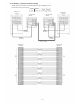
8. PROGRAMMING DATA TABLE INITIAL PROGRAMMING Note. (Mark *) The first station of each exchange becomes the Programming Station: Exchange "A" . . . . . . . . . . . . . . . . . . . . . . . . . No. 200 (100) Exchange "B" . . . . . . . . . . . . . . . . . . . . . . . . . No. 470 (400) Exchange "C" . . . . . . . . . . . . . . . . . . . . . . . . . No. 740 (700) Initial Programming of the Exchange 1. 2. Place program switch on front panel of the CP "ON" Dial operation from station No. 200 (100).
< PROGRAMMING DATA TABLE 1 > Function Table for the System Function Group Function Function code Registered data A Numbering schedules of tie-line system 40 Note of Registration 00 B 00 Select the head number of stations in each exchange from among the followings: A/B/C= 200/470/740 or 100, 200, 300, 400, 500, 600, 700, A/B/C= 100/400/700 800 or 900 C Selection of Calling Tone 00 0: Without Calling Tone 41 Initial programming —— 1: Single tone (0.2 sec.) 2: Calling tone (0.3 sec.
Stations Allowed Access to All Call Stations Allowed Access to Conference Automatic Access to Paging — 43 — Stations Allowed Access to One Shot Output Stations Allowed Access to Make/Break Output Stations Allowed Access to 1/8 Select (or Decimal) Output Stations Allowed Access to 4 Decimal Digits Output Secretary Station No. *1 Master Station No. *1 Transferred Station No. for Group Hunting * 1 Paging Zone No. Group No. for Group Blocking Group No. for Calling Party Indication Programmed Station No.
For Tie-line Unit (EX-610) Stations Allowed Access to All Call Stations Allowed Access to Conference —44— Automatic Access to Paging Stations Allowed Access to One Shot Output Stations Allowed Access to Make/Break Output Stations Allowed Access to 1/8 Select (or Decimal) Output Stations Allowed Access to 4 Decimal Digits Output Secretary Station No. *1 Master Station No. *1 Transferred Station No. for Group Hunting *1 Paging Zone No. Group No. for Group Blocking Group No.
For Tie-line Unit (EX-620) Stations Allowed Access to Conference Automatic Access to Paging —45— Stations Allowed Access to One Shot Output Stations Allowed Access to Make/Break Output Stations Allowed Access to 1/8 Select (or Decimal) Output Stations Allowed Access to 4 Decimal Digits Output Secretary Station No. *1 Master Station No. *1 Transferred Station No. for Group Hunting *1 Paging Zone No. Group No. for Group Blocking Group No. for Calling Party Indication Programmed Station No.
Paging Zone Table Paging Zone Function Code 70 Department First Station No. A B Last Station No. C 01 08(16 ) 15(31) 02 09(17 ) 16(32 ) 03 10(18) 17(33 ) 04 11(19) 18(34 ) 05 12(20 ) 19(35 ) 06 13(21) 20(36 ) 07 14(22) 21(37) Station Numbers Table for Calling Party Indication (Lamp Type) Calling Party Indication Name First Station No. Group No. Last Station No. Function Code 72 1 2 3 4 5 6 7 8 Note.
Group Blocking for Paging Groups Paging Zone Department All Call Paging Group No. No.
Summary Table of Group Blocking (Function Code 71, 81, 82) and Paging Zone (Function Code 70) Note. indicates that registration is not necessary, Stations in Each Group First Station No. Called (Paged and Responding) Group No. Zone No. 01 -21 Calling (Paging) Group No. First Station No. Stations in Each Paging Zone Last Station No. indicates stations not belonging to any group. Stations not belonging to any Zone Last Station No.
PART 2. FUNCTION SELECTION FOR DATA TRANSMITTING AND RECEIVING UNITS 9. SETTING OF CHANNEL SELECT SWITCH OF TRANSMITTING UNIT (DT-E11) AND WORD SELECT SWITCH OF RECEIVING UNIT (DR-B61) NOTE 1. Connect the DT-E11 and DR-B61 to Exchange correctly. (Refer to operation manuals of DT-E11 and DR-B61). 2. Set the function select switches (DIP SWITCH) on CP-63 correctly and be sure to enter initial programming and function registration at programming station No.200. 3.
10.
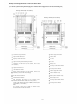
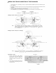
11. SYSTEM DIAGRAM OF DATA TRANSMITTING AND RECEIVING UNITS Tie-line Unit TI-62 Stations (When the exchanges are connected by means of tie-line.) Tie-line Unit TI-62 YR-810 YR-802 or YR-806 Stations Tie-line Unit TI-62 or YR-806 or YR-806 (Data Receiver (Equipment using DR-B61)) (Data Transmitting Unit) In/Out Annunciation (500 contacts) In/Out Annunciation (500 contacts) VTR, ITV, etc.
12. EXPLANATION OF DATA TRANSMITTING UNIT OUTPUT CHANNELS CHANNEL SELECTION FUNCTIONS APPLICATION DESCRIPTION Personel in and out registration can be accomplished at any Master sta- IN/OUT Annunciation tion by using personal numbers. Max. 500 IN/OUT annunciations may be • IN/OUT Annunciation done.
13. EXPLANATION OF DATA RECEIVING UNIT OUTPUT DATA 13-1 Channel 0 (CH.
13-2 Channel 1 (CH. 1) (1) One-shot Make Output (50 contacts) (3) 8-Selectable Make Output (9 units) (5) 4 Decimal Digits Output (9 units) (2) Make/Break Output (100 contacts) (4) Decimal Output (9 units) (6) Pager Control Output (64 contacts) CHANNEL SELECT Switch (Example) (1) One-shot Make Output (2) Make/Break Output (3) 8-Selectable Make Output Unit No. 4 Condition "1" Unit No. 6 Condition "8" (4) Decimal Output (9 units) Unit No.
13-3 Channel 2 (CH. 2) Calling Party Indication (Lamp Type) (1) Each "Calling Station" or "Waiting Station" is shown by Each Lamp of Indication. Total Number of Station with Indications: 4 Stations (Groupsl/Channel [8 Stations (Groups)/2 Channels] Total Number of Calling Stations: Max. 120 Stations/Each Indication Relay Output No. Data Receiver Station No. with Indication CHANNEL SELECT Switch Group 1 Group 2 Group 3 Each Relay Output shows "Calling Station No.
13-4 Channel 3 (CH. 3) Calling Party Indication (Lamp Type) (2) Each "Calling Station" or "Waiting Station" is shown by Each Lamp of Indication. Total Number of Station with Indications: 4 Stations (Groupsl/Channel [8 Stations (Groups)/2 Channels] Total Number of Calling Stations: Max. 120 Stations/Each Indication CHANNEL SELECT Switch Each Relay Output shows "Calling Station No.
Appendix. Instructions for building the CP-63 in the EXES-5000 1. The CPU-55/56 differ from the CP-62/63 in dial operation. Function CPU-55 CPU-56 CP-62 CP-63 X: 1 ~ 9, Y: 1 ~ 8, 0 (Clear) X: 1 ~ 9, Y: 1 ~ 8, 0 (Clear) Continuous Calling Tone One-touch Response 8 Selectable Make Output X: 1 ~ 9, Y: 0~ 7 2. Set the DIP switch SW-E-5 (change-over of Privacy and Continuous Calling Tone) to OFF (Privacy). Set the other DIP switches according to the necessity. 3.
TOA ELECTRIC CO, LTD.