Rev. A INSTRUCTION MANUAL CEILING SPEAKER SYSTEM F-122CU Please follow the instructions in this manual to obtain the optimum results from this unit. We also recommend that you keep this manual handy for future reference.
TABLE OF CONTENTS 1. SAFETY PRECAUTIONS ............................................................................... 3 2. GENERAL DESCRIPTION ............................................................................. 3 3. FEATURES .......................................................................................................... 4 4. NOMENCLATURE AND DIMENSIONS ..................................................... 4 5. MOUNTING HARDWARE INSTALLATION .............................................
1. SAFETY PRECAUTIONS • Be sure to read the instructions in this section carefully before use. • Make sure to observe the instructions in this manual as the conventions of safety symbols and messages regarded as very important precautions are included. • We also recommend you keep this instruction manual handy for future reference.
3. FEATURES • Bass-reflex speaker system designed to provide a wide frequency range and high power handling capability. • Wide-dispersion flush-mount ceiling speaker design employs unique acoustic construction to realize a wide area of coverage. Uniform sound output levels are achievable not only directly under the speaker, but also over a wide radius. • Because the speaker is provided with both low- and high-impedance operating capability, it can be used in many different applications.
. MOUNTING HARDWARE INSTALLATION Before mounting the speaker, determine the most appropriate method for the existing ceiling structure. Be sure to use an optional HY-TB1 Tile Bar Bridge in combination with the supplied ceiling reinforcement ring. [Installation view on Drop Ceilings] Because the bridge rails are 603 mm (23 47/64") in length, be sure to match them to the ceiling tile size during installation.
Step 1. Cut a ø200 mm (7 7/8") hole in the ceiling. ø200 ±5 mm (7 7/8 ±13/64") Use the supplied paper pattern to position and trace the hole. Ceiling panel Step 2. Install the HY-TB1 in the ceiling. Loosen the two reinforcement ring mounting screws in each tie-plate to the point that they do not fall out of their holes. Tie-plate HY-TB1 (optional) Bridge rail Tie-plate mounting screw Reinforcement ring mounting screws (Leave these screws loose.
Step 3. Place the supplied reinforcement ring on the ceiling panel. Fold the reinforcement ring in half* and insert it through the mounting hole in the ceiling panel, then open it with its tabs facing up. Place the ring on the ceiling panel aligning it with the mounting hole. Mounting hole * The reinforcement ring is too large to be inserted into the mounting hole unless folded.
Step 5. Attach a safety wire to prevent the speaker from accidentally falling. To attach, tie one end of the supplied safety wire around the speaker's safety wire hook, and tie its snap ring around the installed HY-TB1 or a solid structure. Note When there is no gap between the bridge rails and the ceiling panel, to secure the safety wire, tie the wire around a solid structure (pipe, building frame, etc.).
6. WIRING 6.1. Using the Speaker in UL1480 Category UUMW Choke bracket Remove the choke bracket and the cover plate from the speaker. Cover plate Note The removed choke bracket is not used. Flexible metal conduit (3/8" or 1/2") Cover plate Conduit fitting To install this speaker as a fire alarm signaling service UUMW, use flexible conduit of 3/8 or 1/2 inch trade size and the UL514B listed conduit fitting of the same trade size.
6.2. Using the Speaker in UL1480 Category UEAY only 6.2.1. Wiring through hard or flexible conduit Note The choke bracket equipped with the speaker has not been evaluated by UL, for conduit connection and UL514B Standard. Flexible conduit of 3/8 or 1/2 inch trade size and the UL514B conduit fitting of the same trade size can also be used. For the method of conduit connection, refer to p. 9. Loosen the screw to allow the speaker cable to pass through.
6.2.2. Wiring with naked cables Loosen the screw to allow the speaker cable to pass through. Choke bracket Retighten the screw to fix the speaker cable. Plug the wired input connector into the speaker's socket, then pull the speaker cable from the choke bracket. (For wiring the input connector, refer to p. 12.) Note Ensure that the speaker cable is securely fixed.
7. CABLE CONNECTION TO INPUT CONNECTOR Recommended cable types • Solid copper wire: ø1.0 – ø1.6 mm (equivalent to AWG 18 – 14) • Stranded copper wire: 0.75 – 2.5 mm2 (equivalent to AWG 18 – 14) Cover mounting screw Step 1. Loosen the 2 cover mounting screws, and rotate the connector cover in the direction indicated by the arrow in the figure at right. Speaker unit Connector cover Detachable input connector Step 2.
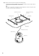
8. SPEAKER INSTALLATION Caution Before mounting, check to be sure that the speaker's 3 mounting tabs are turned inside the unit as shown in the figure. If turned outward, the speaker cannot be inserted through the mounting hole. In Out Mounting tab Step 1. Insert the speaker through the mounting hole till it contacts the ceiling panel. While doing so, avoid directly touching the speaker's diffuser section.
Step 3. Set the input power. Turn the input selector switch (on the unit's front) to set it to the desired input impedance. (Factory-preset to 170 Ω.) Note Setting positions "8 Ω" and "16 Ω" can be used in UL1480 Category UEAY only. Step 4. Attach the front grille. Align the tabs (3 places) on the back side of the grille with the corresponding notches in the unit, then rotate the grille to full stop in the direction indicated by the "LOCK" arrow.
9. REMOVING THE SPEAKER FOR MAINTENANCE 9.1. Detaching the Front Grille 1 Turn the front grille counterclockwise to full stop, then lightly pull it downward. Tip The front grille employs a double-locking system. If the grille cannot be detached when lightly pulled downward, it likely has not yet been fully rotated back to the detachment position. In such cases, take care to rotate the grill fully counterclockwise in order to release the lock. Unlock Front grille 2 Pull lightly. 9.2.
10. REPAINTING THE SPEAKER Follow the procedure below when repainting the front grille: Step 1. Clean the front grille before painting. Wipe with a soft cloth dampened in a detergent. Caution Do not use thinner or other volatile liquids to clean the grille. Step 2. Spray on a uniform, thin coat of paint. Cautions • Avoid painting with a roller or brush, as the grille mesh holes could become clogged with paint. • Use appropriate spray paints for the front grille (grille and frame) materials.
12. SAFETY AGENCY COMPLIANCE This product is for indoor use only. S8460 16VP Fire Protective Signaling Speaker 16VP Signaling Speaker The F-122CU's front-mounted rotary switch permits selection of speaker handling power (wattage) on 25 V or 70 V line operation or low impedance (8 Ω or 16 Ω) operation. Depending on the switch settings, the unit complies with the different UL Categories as follows. Note: Setting to the "8 Ω " and "16 Ω " positions allows the unit to comply with Category UEAY only. 12.1.
13. SPECIFICATIONS Enclosure Rated Input Power Handling Capacity Impedance Frequency Response Speaker Component UL Code Mounting Hole Input Terminal Usable Cable Finish Dimensions Weight Bass reflex type 30 W (High Impedance) Continuous pink noise: 60 W (8 Ω), 30 W (16 Ω) 70 V line: 170 Ω (30 W), 330 Ω (15 W), 1 kΩ (5 W), 3.3 kΩ (1.5 W), 10 kΩ (0.5 W) 25 V line: 170 Ω (3.7 W), 330 Ω (1.9 W), 1 kΩ (0.6 W), 3.3 kΩ (0.2 W), 10 kΩ (0.
Printed in Indonesia 533-06-090-20