
Power Supply User Manual


10
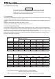
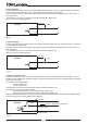
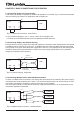
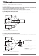
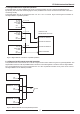
3.7.7 Input/Output connector information
The FPS1000 series uses male connector PCIB24W9M400A1, Positronic connector. To mate FPS1000
series to the load circuitry, use female connector PCIB24W9F400A1-S1031, Positronic connector.
Refer to Table 3-4 and to the Outline drawing in chapter 2 for the connector pinout description.
Table 3-4: Rear In/Out connector pins function description
3.7.8 REPACKAGING FOR SHIPMENT
The original packaging material is reusable. If the original package is not available, contact the Lambda
Sales or service facility near you for details on obtaining suitable packaging and shipping information.
To ensure safe transportation of the instrument, it is recommended to use the original package.
Please attach a tag to the power supply describing the problem and specifying the owner, model number
and serial number of the power supply.
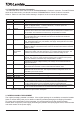
Pin No Function Description
1,2,4 +V Positive output voltage. Maximum current capacity: 24A/contact.
3,5,6 -V Negative output voltage. Maximum current capacity: 24A/contact.
7 On/Off control
8
+Sense
9 DC_OK
10 Signal_Return
11 AC_Fail
12
Over
Temperature
Alarm
13 -Sense
14 V_Trim
15 CS
16 +12V Auxiliary
17 SDA
Serial Data used in the I
2
C interface option. Refer to the I
2
C interface description.
18 SCL
Serial Clock used in the I
2
C interface option. Refer to the I
2
C interface description.
19,20,21 A0, A1, A2
I
2
C interface address lines. Refer to the I
2
C interface description in Chapter 7.
22 ACG
23 AC Line
24 AC Neutral
Turns the output to On and Off by electrical signal or dry contact between pin 7
and pin 10 (Signal Return). 0~0.6V or Short: On, 2~15V or Open: Off.
The maximum source current is 2.6mA.
Positive sensing. The +Sense signal should be connected to the positive terminal
of the load. The +Sense and -Sense leads should be twisted pair to minimize noise
pick-up effect. The maximum load wires drop compensation is 1V/wire.
Return for the following control and supervisory signals: On/Off, DC_OK,
Over_temperature Alarm, AC_Fail, Auxiliary 12V supply. The Signal return is isolated
from the output terminals.
Open collector signal, referenced to pin 10 (Signal Return). On when Vout≥80%+/-
5% of its rated value. The maximum sink current is 10mA and the maximum
external voltage is 15V.
Open collector signal, referenced to pin 10 (Signal Return). On when the internal
temperature is within safe limit, Off approx. 10°C below Thermal shut down. The
maximum sink current is 10mA and the maximum external voltage is 15V.
Open collector signal, referenced to pin 10 (Signal Return). On when the input
voltage is ≥85Vrms. The maximum sink current is 10mA and the maximum external
voltage is15Vdc.
Negative sensing. The -S signal should be connected to the negative terminal of
the load. The -S and +S leads should be twisted pair to minimize noise pick-up
effect. The maximum load wires drop compensation is 1V/wire.
Connection for output voltage trimming. The voltage can be trimmed within its
range specifications.
Current sharing signal. When units are connected in parallel, the CS pins of the
units should be connected to allow current balance between units.
Auxiliary voltage output, 11.2~12.5V, referenced to pin 10 (Signal Return). The
maximum load current is 0.25A. This output has built in Oring diode and is not
controlled by the On/Off control.
AC Ground connection, refer to the safety instructions for safety standards requirements.
For "/P" models the AC Ground is connected via the front panel IEC inlet.
AC Line connection, refer to the safety instructions for safety standards requirements.
For "/P" models the AC Line is connected via the front panel IEC inlet.
AC Neutral connection, refer to the safety instructions for safety standards requirements.
For "/P" models the AC Neutral is connected via the front panel IEC inlet.