
Power Supply User Manual


21
The PCF8591 slave address is:
The PCF8591 device initially requires a control byte to be written to the configuration register.
The control byte is as follows:
When a single channel is to be read, A,B,C and D should be determined as follows:
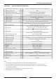
Refer to the following table for the scaling of the A/D channels:
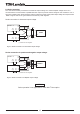
7.4.3 Analog functions
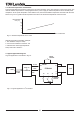
Analog functions are provided by a single PCF8591, 4-channel 8-bit A/D converter. When this device is read by the
serial buscontroller it provides an 8-bit word with the following information:
Channel 1: Output voltage, channel 2: Output current, channel 3: Internal temperature.
Bit 7 6 5 4 3 2 1 0
Value 1 0 0 1 A2 A1 A0 R/W
Bit 7 6 5 4 3 2 1 0
Value 0 A 0 0 0 B C D
A/D channel A B C D
Voltage 0 0 0 0
Current 0 0 0 1
Temperature 0 0 1 0
To read all channels with a single control byte, A and B have to be "1", C and D have to be "0". This control byte
sets the device so that on each successive read the data from the next A/D is read.Thus, the first result from a
sequence of reads should not be considered.
Note that on each read, a conversion is started for a particular channel and the result will be read from the previous channel.
7.4.4 A/D Scaling
The A/D readback has to be scaled to obtain a correct value for the voltage, current and the temperature. Note that
the voltage reading is made inside the power supply unit before the "Oring" diode and is typically 0.5V higher than
the actual output voltage.
The following scaling should be employed:
VALUE = BYTE VALUE x RESOLUTION
The measurement range is from 0 to the maximum value listed in the range column. The resolution or scale of
reading is linear over the entire range and provides a linear output on the A/D converter.
7.5 Measurements and calculation examples
7.5.1 Output voltage readback
The voltage before the "Oring" diode is measured and can be read from the A/D converter. This voltage is higher
than the voltage at the output terminals by 0.5V typically.
Model: FPS 1000-48/S
1. Output voltage (at the output terminals): 48.0V
2. Voltage before the "Oring" diode: 48.0V+0.5V=48.5V
3. .Hex readback: CE (1100 1110).
4. Convert the hex readback to decimal: 206
5. Calculate measured Vout: Vout=206*0.2344=48.286V
7.5.2 Output current readback
The output current is sensed by an internal shunt and measured by an A/D converter. Refer to the following examplefor
current readback calculation.
1. Actual output current: 21.0A
2. Hex readback: E0 (1110 0000).
3. Convert the hex readback to decimal: 224
4. Calculate measured Iout: Iout=224*0.0977=21.884A.
FPS1000 Instruction Manual
FPS1000-24/S
FPS1000-48/S
FPS1000-32/S
FPS1000-12/S
0~15V
0~80A
0~100°C
0.0586 V/Bit
0.312 A/Bit
0.391°C/Bit