
Power Supply User Manual


36
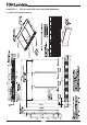
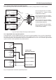
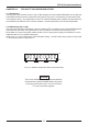
Fig 13-5: Remote On/Off control at parallel operation
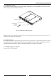
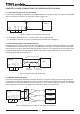
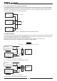
Fig 13-6: Series connection for increased output voltage
13.1.4 Remote On/Off control at parallel operation
The paralleled racks can be turned On or Off via a single On/Off control. Refer to Fig 13-5 for typical application.
The Signal Return function of all the paralleled racks should be connected together to create a common Signal
Return bus. The Signal Return bus may be connected to the -V or the +V potential or floated. In any case do not
connect the Signal Return bus to different potentials.
13.2 Series operation
Two FPS-S1U racks with the same output voltage rating can be connected in series to increase the output voltage
or to create a bipolar voltage source. It is recommended to connect diodes in parallel with each output to prevent
reverse voltage in case of failure in one of the power supplies.
Each diode should be rated to at least the power supply rated output voltage and output current.
Refer to Fig 13-6 and 13-7 for a typical series connection of power supplies.
(*) Diodes are user supplied
LOAD
+V
+S
-S
-V
+S
-S
+V
-V
+V
+S
-S
-V
(*)
(*)
FPS-S1U #1
FPS-S1U #2
11
SIG.
RTN
ON/
OFF
C
ON/
OFF
B
ON/
OFF
A
515 25
11
SIG.
RTN
ON/
OFF
C
ON/
OFF
B
ON/
OFF
A
515 25
ON OFF
FPS-S1U #1
SIG.
RETURN
ON/OFF
A, B, C
FPS-S1U #2
SIG.
RETURN
ON/OFF
A, B, C
FPS-S1U #3
SIG.
RETURN
ON/OFF
A, B, C
5, 15, 25
11
11
11
5, 15, 25
5, 15, 25
2.6 mA / Installed unit
2.6 mA / Installed unit
2.6 mA / Installed unit
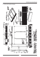
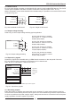
Fig 13-7: Series connection for Bipolar output voltage
(*) Diodes are user supplied
LOAD
FPS-S1U #1
FPS-S1U #2
+V
+S
-S
-V
+V
-V
+V
+S
-S
-V
(*)
(*)
COMMON
11
SIG.
RTN
ON/
OFF
C
ON/
OFF
B
ON/
OFF
A
515 25
11
SIG.
RTN
ON/
OFF
C
ON/
OFF
B
ON/
OFF
A
515 25
CAUTION
Series operation is not applicable for units with I
2
C bus option.