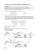
OPERATING INSTRUCTIONS IP Series DUAL POWER AMPLIFIERS IP-600D IP-450D IP-300D TABLE OF CONTENTS 1. 2. 3. 4. 5. SAFETY PRECAUTIONS GENERAL DESCRIPTION FEATURES HANDLING PRECAUTIONS NOMENCLATURE AND FUNCTIONS Front panel Rear panel 6. INSTALLATION 7. CONNECTIONS 2 4 4 4 5 6 7 8 8. CLEANING THE FILTER 9. REMOVING THE HANDLE 10. INSTALLING AN OPTIONAL MATCHING TRANSFORMER LT-101 11. BLOCK DIAGRAM 12. TABLE FOR PROTECTION CIRCUIT ACTIONS 13. APPEARANCE AND DIMENSIONS 14.
1. SAFETY PRECAUTIONS Be sure to read the instructions in this section carefully before use. Make sure to observe the instructions in this manual as the conventions of safety symbols and messages regarded as very important precautions are included. We also recommend you keep this instruction manual handy for future reference.
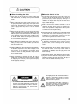
When Installing the Unit Never plug in nor remove the power supply plug with wet hands, as doing so may cause electric shock. When unplugging the power supply cord, be sure to grasp the power supply plug; never pull on the cord itself. Operating the unit with a damaged power supply cord may cause a fire or electric shock. When moving the unit, be sure to remove its power supply cord from the wall outlet.
2. GENERAL DESCRIPTION TOA's IP series dual power amplifiers feature high durability, high quality sound and high output power (IP300D: 300 W, IP-450D: 450 W, IP-600D: 600 W - when a 4 load connected). Input/output levels and other functions can be remotely controlled from external equipment. (An interface unit is required. For details, contact your TOA dealer.) The amplifier is ideal for use in store sound systems, permanently-installed sound systems, and other sound systems. 3.
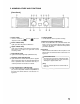
. NOMENCLATURE AND FUNCTIONS [ Front Panel ] Power switch Power is switched on depression of this switch. Carrying handle and off with each Can be detached. Refer to p.9 when removing. Input level control (pushlock type) Power indicator lamp Lights green when the power is switched on. Signal indicator lamp Lights green regardless of the input level control setting when there is an input of a signal with a level exceeding -30 dB. Peak indicator lamp Clicks at each dB mark on the scale when rotated.
[Rear panel] Input terminal Level control switch Electrically-balanced input terminals. The 3P screw terminal is connected in parallel with a balanced phone jack. Also, the input can be converted into a transformerbalanced input using an optional matching transformer LT-101. Usually, set this switch to OFF. When an interface unit is connected, shifting this switch to ON permits external input level adjustment.
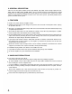
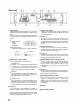
6. INSTALLATION Carefully note heat radiation when installing the unit. These power amplifiers are equipped with a cooling fan. To avoid heat buildup, ensure that the rear of the unit is at least 10 cm away from the wall surface. When mounting the unit in the rack, the inside of the rack must be well ventilated. To accomplish this, keep the rear side of rack open (no panel is mounted), and mount a ventilation panel of over 1-unit size in the uppermost and lowermost rack positions on the rack front.
7. CONNECTIONS 1. Switch off the amplifier power. 2. Unscrew the output terminal cover. 3. Strip 10 mm of insulative jacket from the end of the speaker cable, as shown in the figure at right. 4. Connect speaker cables to the output terminals. 5. Fit the output terminal cover in place. [Precautions] Be sure to fit the output terminal cover in place. Take care that the naked wires of the speaker lines do not contact the unit's chassis. Refer to the figures below for connections for each output mode.
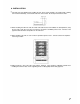
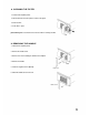
8. CLEANING THE FILTER 1. Switch off the amplifier power. 2. Pull the filter from the front panel as shown in the figure. 3. Clean the filter. 4. Fit the filter in place. [Precautions] Make sure that the fan is turned off when removing the filter. Filter 9. REMOVING THE HANDLE 1. Switch off the amplifier power. 2. Remove the handle cover. 3. Remove two screws holding the handle to the amplifier. 4. Remove the handle. Handle 5. Install the supplied screws (M4x20). Handle cover 6.
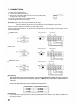
. INSTALLING AN OPTIONAL MATCHING TRANSFORMER LT-101 [ CAUTION ] THESE SERVICING INSTRUCTIONS ARE FOR USE BY QUALIFIED PERSONNEL ONLY. TO AVOID ELECTRIC SHOCK, DO NOT PERFORM ANY SERVICING OTHER THAN THAT CONTAINED IN THE OPERATING INSTRUCTIONS UNLESS YOU ARE QUALIFIED TO DO SO. REFER ALL SERVICING TO QUALIFIED SERVICE PERSONNEL. 1. Attach sleeves supplied with the transformer to the transformer. 2. Remove case fixing screws to remove the case. 3.
12. TABLE FOR PROTECTION CIRCUIT ACTIONS Symptom Excessive current flow due to overload Action Current limiter operates when load resistance is Remove overload. ) (STEREO/PARALLEL) or Unusual DC voltage output Speaker loads cut by output relay. (BTL) load is connected. Check short circuit of speakers and lines. Switch power off, connect correct load, and switch power on. Check ventilation and overload. temperature drops. Protection circuit Contact your TOA indicator lights. dealer.
14. SPECIFICATIONS Model No. Output 20 Hz - 20 kHz IP-300D IP-450D STEREO RL=4 300 W 450 W 600 W RL=8 200 W 300 W 400 W RL=8 600 W 900 W 1200 W BTL Frequency Response Total Harmonic Distortion 8 , 1 kHz 8 , 20 Hz - 20 kHz IP-600D 20 Hz - 20 kHz (+0 dB, -0.5 dB) 0.01% 0.1% Intermodulation Distortion 0.03% 60 Hz : 7kHz= 4:1, 8 Input Sensitivity + 5.3 dB (1.42 V) ±0.5 dB (8 , input level control in maximum position) + 2.2 dB (1.00 V) ±0.5 dB + 4.0 dB (1.23 V) ±0.