PowerDual iQ 18B USER MANUAL
CONTENTS 1. Introduction............................................................................................................... 5 2. Unpacking................................................................................................................. 5 3. Connectors/Cabling ................................................................................................. 5 4. Polarity Checking .....................................................................................................
1. Introduction Thank You for purchasing Tannoy PowerDual™ iQ i8B. The iQ 18B is a dedicated sub-woofer designed for high definition sound reinforcement at low frequencies. It comprises an 18” driver in a horn-loaded cabinet, giving increased efficiency and improved LF output. For optimal performance, the iQ 18B has been designed to operate in conjunction with the iQ 10 mid/high horn-loaded cabinet, where the system is controlled by a dedicated loudspeaker management system TDX2.
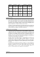
CABLE RUN (m) 10 25 50 100 C.S.A. OF EACH CONDUCTOR (mm) 2.5 4.0 6.0 2.5 4.0 6.0 2.5 4.0 6.0 2.5 4.0 6.0 CABLE RESISTANCE Ω Ω 0.14 0.09 0.06 0.35 0.22 0.14 0.69 0.43 0.29 1.38 0.86 0.58 % POWER LOSS INTO 8Ω Ω LOAD % POWER LOSS INTO 4Ω Ω LOAD 1.7 1.1 0.73 4.3 2.7 1.8 8.6 5.4 3.6 17.0 11.0 7.2 3.5 2.2 1.5 8.6 5.4 3.6 17.0 11.0 7.2 35.0 22.0 14.0 4. Polarity Checking It is most important to check the polarity of the wiring.
For optimal performance the PowerDual™ iQ 18B has been designed to operate with PowerDual™ iQ 10 mid/high cabinet, where overall system control is achieved by utilising the TDX2 system controller. The TDX2 has been factory preset to provide the recommended cross-over points, delays and overall system balance. Please refer to the TDX2 manual for operation. If you intend using an alternative loudspeaker management system (e.g.
9. Positioning When a bass loudspeaker is used in an environment with boundary surfaces, its placement affects its frequency response. When such effects are properly understood, they can be used to great effect in producing the desired sound quality without the aid of additional amplification. Consider Figure 8a in the diagram below, here we see a loudspeaker in free field or anechoic conditions. We measure its sound pressure level at a distance D, and refer to this as our reference level, or 0 dB SPL.
10. Flying Convenient flying points are provided on the iQ 18B which will allow the optional flying equipment to be used, as shown in Figure 10a. In the addition to flying the iQ 18B by itself, it can also be flown in conjunction with Tannoy iQ 10 Mid/High unit. They can also be configured to be flown double. Please refer to the following sections for more detailed instructions. A pole mount is also provided for flying a mid/high cabinet in the air.
.1. Flying an iQ 18B To fly the iQ 18B by itself, the following accessories are required: SR18 Side Rail Kit and SCB Beam Kit. The flown system is assembled as shown in Figure 10b. The SR18 side rail kit is screwed to the side of the cabinet using the screws provided (1). The SCB Beam Kits are then placed above and below the speaker (2). The Lynch Pin is inserted into the holes of the side rail kit top and bottom (3) and the Pin folded to secure it in place (Figure 10c). Figure 10c Figure 10b 10.2.
To fly two iQ 18Bs, the following accessories are required: 2 × SR18 Side Rail Kit, 2 × SCB Beam Kit and 1 × JK1 Jointing Kit. The flown system is assembled as shown in Figure 10d. The SR18 side rail kit is screwed to the side of each cabinet using the screws provided (1). The JK1 Jointing Kit is slotted between two SCB Beam Kits for both the top and bottom (2). The combined SCB Beam Kits are placed above and below the speaker (3).
To fly the iQ 18B with the iQ 10 Mid/High unit (with optional trapezoidal cabinet), the following accessories are required: SR18/10 Side Rail Kit and SCB Beam Kit. The flown system is assembled as shown in Figure 10e. First, the SR18/10 side rail kit is screwed to the side of both the iQ 18B and iQ 10 cabinets using the screws provided (1). The SCB Beam Kits are placed above and below the speaker assembly (2).
To fly double combined iQ 18B with the iQ 10 Mid/High unit (with optional trapezoidal cabinet), the following accessories are required: 2 × SR18/10 Side Rail Kit, 2 × SCB Beam Kit and JK1 Jointing Kit. The flown system is assembled as shown in Figure 10g. First, the SR18/10 side rail kit is screwed to the side of each iQ 18B and iQ 10 cabinet using the screws provided (1). The JK1 Jointing Kit is slotted between two SCB Beam Kits for botht he top and bottom (2).
Anechoic Frequency Response, with TDX2 Controller Impedance Response, Passive 12.
Frequency Response (+/- 3dB) 39Hz - 230Hz, (-10dB Point) 33Hz Recommended Amplifier Power 600 - 1200 watt / 8 ohm Power Handling Average (2) 600 watt Sensitivity (1) 2.83 volt @ 1m (20-180Hz) Programme 1200 watt 104dB (half space) Maximum SPL (3) @ 1m Average 132dB Peak 138dB Impedance Nominal Minimum 8.0Ω 7.0Ω 2nd Harmonic 1.91% 0.78% 3rd Harmonic 0.59% 1.11% 2nd Harmonic 0.56% 0.37% 3rd Harmonic 0.47% 0.
13. iQ 18B Service Parts and Accessories Part Number Description 7900 0954 7900 0955 Driver Kit Type 4504 Recone Kit Type 4504 8001 2070 8001 2080 8001 2090 8001 2180 8001 2190 SR 18 Side Rail Kit SR 18/10 Side Rail Kit JK1 Jointing Kit SCB Single Cabinet Beam EBS10 Eyebolt Set 8000 0727 8000 0728 8000 0729 TDX2 Digital loudspeaker management system 60-250V - UK TDX2 Digital loudspeaker management system 60-250V - EUR TDX2 Digital loudspeaker management system 60-250V - USA 14.
Tannoy Limited, Professional Division, Coatbridge, Strathclyde, ML5 4TF, Scotland. Tel: +44 (0) 1236 420199 Fax +44 (0) 1236 428230 e-mail: prosales@tannoy.com Website: www.tannoy.com Tannoy / TGI North America Inc., 335 Gage Avenue, Suite 1, Kitchener, Ontario, Canada N2M 5E1. Tel: (519) 745-1158 Fax: (519) 745-2364 e-mail: inquiries@tgina.com Website: www.tannoy.com Tannoy Nederland b.v., Anthonetta Kuijlstraat 19, 3066 GS Rotterdam. Tel: (010) 286 0554 Fax: (010) 286 0431 e-mail: info@tannoy.