INSTRUCTION MANUAL NETWORK COMBINATION DOME CAMERA N-CC2564 Thank you for purchasing TOA's Network Combination Dome Camera. Please carefully follow the instructions in this manual to ensure long, trouble-free use of your equipment.
TABLE OF CONTENTS 1. SAFETY PRECAUTIONS ............................................................................... 3 2. LIST OF INCLUDED COMPONENTS AND PARTS ............................... 4 3. GENERAL DESCRIPTION ............................................................................. 5 4. FEATURES .......................................................................................................... 5 5. HANDLING PRECAUTIONS ...................................................................
1. SAFETY PRECAUTIONS • Be sure to read the instructions in this section carefully before use. • Make sure to observe the instructions in this manual as the conventions of safety symbols and messages regarded as very important precautions are included. • We also recommend you keep this instruction manual handy for future reference.
CAUTION Indicates a potentially hazardous situation which, if mishandled, could result in moderate or minor personal injury, and/or property damage. When Installing the Unit • To avoid electric shocks, be sure to switch off the power before power supply wiring work. Failure to do so may result in electrical shock. • Leave the installation of the unit to your TOA dealer because the installation requires expert experience and skills. If the unit falls, this could cause personal injures.
3. GENERAL DESCRIPTION The N-CC2564 Network Combination Dome Camera can be connected directly to a LAN (10BASET/100BASE TX). Since it can simultaneously transmit MPEG-4 and JPEG data, smooth moving images can be monitored and high-definition still images can be monitored and recorded. The N-CC2564 can transmit sub-band ADPCM or PCM quality voice.
• Installing the camera cables in close proximity to fluorescent lamps or other electrical appliances can downgrade the picture quality. • If there is a strong electric or magnetic field near the camera, such as television transmission antennas, motors or transformers, this may distort or roll the monitor picture. In such cases, run the entire wiring route through metal conduit tubing. • Before applying the power to the camera, be sure to complete all connections between the camera and related equipment.
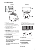
6. NOMENCLATURE [ Front view ] [ Top view ] 2 3 4 9 1 5 6 1 1 7 NETWORK COMBINATION DOME CAMERA model N-CC2564 CU 24V 50 / 60Hz Max.16A 10 8 9 (1) Power Cable Connects to the power supply. (2) Network Terminal (10BASE-T/100BASE-TX) Connects to the 10BASET/100BASE-TX using the supplied LAN adapter. (3) Video Output Terminal (VIDEO OUT) Outputs the Video signals.
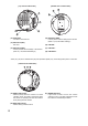
[ Bottom view of Camera Unit ] [ Top view of Camera Unit ] 17 13 18 16 14 15 12 (12) Safety Wire Connects to the base unit. (15) DIP Switch (SW2) Used to perform various settings of the camera. (Refer to p. 32; DIP Switch Settings.) (13) DIP Switch (SW1) Not used. (16) COM SW * (14) DIP Switch (SW2) Used to perform various settings of the camera. (Refer to p. 32; DIP Switch Settings.) (17) COM LED * (18) COM PORT * * Parts (16)-(18) are for maintenance purposes (firmware update) only.
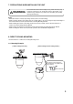
7. PRECAUTIONS WHEN INSTALLING THE UNIT WARNING The Combination Dome Camera weight 2.0 kg. Select the heavy-duty mounting surface that can structurally support the weight of the camera. Doing otherwise may result in the unit falling and possibly causing personal injury. Notes • Mount the camera to a heavy-duty ceiling surface (such as concrete ceiling).
8.2. Mounting Procedures 1. Mount the base unit to the ceiling. First fix two of the base unit mounting holes as shown below. Since no mounting screws are supplied with the camera, prepare them separately. Use screws with a nominal diameter of 4 mm and a length of over 25 mm. Note: When routing cables over the ceiling surface, securely fix all 4 of the base unit mounting holes to the ceiling. Camera direction Camera direction Ceiling surface Secure these two holes first.
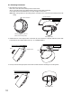
4. Perform DIP SW settings on the camera unit. (For details, please refer to p. 32; "DIP Switch Settings.") 5. Attach the safety wire from the camera unit to the wire mounting hole of the base unit. Wire mounting bracket 6. Align the positioning mark on the base unit with that on the camera unit.
7. Align the positioning marks, then push the camera unit up into the base unit. Push up Screw section inside the base unit is to be inserted into the oval hole in the camera unit. Note Take care not to pinch the safety wire between the camera unit and base unit to avoid damage to the camera. Note When mounting the camera unit to the base unit, mount it straight till it is attached to the base unit correctly. Mounting it at an angle may cause damage to the camera unit.
9. Tighten 2 camera unit mounting screws. Tighten 10. Align the positioning mark on the ceiling mounting cover with that on the base unit. Align the marks Ceiling mounting cover C-BC511C C-BC511C-S 11. Turn the ceiling mounting cover clockwise pushing it up to the base unit until it locks into place.
9. MOUNTING THE CAMERA TO A WEAK CEILING PANEL Use the optional C-BC511C or C-BC511C-S Ceiling Mounting Cover and the optional C-BC511A Ceiling Mounting Bracket. Notes • Use the cover and the anchor whenever the space between suspended ceiling panel and upper ceiling exceeds a height of 100 mm. • The ceiling panel to which the camera will be mounted must be 9 - 40 mm in thickness. • Be sure to use the supplied safety wire.
9.2. Mounting Procedures 1. Make a mounting hole of ø140 mm in the ceiling panel. 2. Install the anchor bolt for ceiling mounting bracket and anchor bolt for safety wire into the upper ceiling. Notes • The anchor bolt for ceiling mounting bracket must be aligned with the center of the mounting hole of ø140 mm in the ceiling panel, and must not project from the ceiling surface. • If an existing anchor bolt is available nearby, it can be substituted for the anchor bolt for safety wire.
6. Attach the supplied safety wire to the base unit. Use screws M3 x 8 tightened to the base unit. 7. Attach the safety wire connected to the base unit to the ceiling mounting bracket. 8. For subsequent procedures, follow the steps 1 – 11 on p. 10 – 13.
10. FLUSH CEILING MOUNTING • Use the optional C-BC511U or C-BC511U-S Flush Ceiling Mounting Bracket. • Flush mounting can be used to reduce the camera's exposed area. Use the optional C-BC511U or CBC511U-S Flush Ceiling Mounting Bracket when mounting cameras to gypsum board ceilings or other weak ceiling panel materials in which mounting screws cannot be securely inserted. Notes • Use the bracket whenever the space between suspended ceiling panel and upper ceiling exceeds a height of 250 mm.
10.2. Mounting Procedures 1. Make a mounting hole of ø230 mm in the ceiling panel. 2. Install the anchor bolt for flush ceiling mounting bracket and anchor bolt for safety wire into the upper ceiling. • The anchor bolt for flush ceiling mounting bracket must be aligned with the center of mounting hole of ø230 mm in the ceiling panel. • Use the pattern paper supplied with the C-BC511U or C-BC511U-S bracket to determine the anchor bolt length and mounting surface height.
4. Attach the supplied safety wire to the anchor bolt for safety wire. 5. Attach the flush ceiling mounting bracket to the end of safety wire. Upper ceiling 4 Anchor bolt flush ceiling mounting bracket Notch Ca dir mer ec a tio n 5 6. Release the lock on the hinged portion of the base unit and connect the composite cable and power cable extending from the base unit. (For details, please refer to p. 30; "CONNECTIONS.
7. Place the flush ceiling mounting bracket in the ceiling behind the ceiling panel by inserting it through the mounting hole in the ceiling panel, then secure the bracket using the three supplied ceiling mounting screws. Turning the mounting screws clockwise clamps the ceiling holding plate to the ceiling panel. Ensure that the notch in the bracket is pointing in the camera's intended direction.
10. Attach the camera unit to the base unit. Align the positioning mark on the camera unit with that on the flush ceiling mounting bracket. Align the notch with mark. 11. Perform steps 7 – 9 on p. 12 – 13. 12. Align the positioning mark on the supplied dome cover with the notch in flush ceiling mounting bracket. 13. Turn the dome cover counterclockwise pushing it up to the flush ceiling mounting bracket until it locks into place. 12 Align the notch with mark.
11. CEILING SUSPENSION Use the optional C-BC511P Ceiling Suspension Bracket in combination with the optional C-BC511C or CBC511C-S Ceiling Mounting Cover when suspending the camera from a ceiling. Notes • Be sure to mount the ceiling suspension bracket using the supplied safety wire. • Be sure to use the specified screws to mount the Network Combination Dome Camera and ceiling suspension bracket, and ensure that they are securely mounted without any play. 11.1.
11.2. Mounting Procedures 1. Determine the suspending position, then make a mounting hole of ø50 – 60 mm in the ceiling plate. 2. Install the anchor bolt for safety wire into the upper ceiling. Note: If an existing anchor bolt is available nearby, it can be substituted for the anchor bolt for safety wire. 3. Separately prepare a suspension plate, and cut out the necessary hole in a way best suited to the plate material.
5. Attach the suspension pipe (saddle bracket and footing) to the suspension plate. Note: Ensure that the installed suspension pipe faces in the intended camera orientation. [Mounting hole dimensional diagram] 81 Footing Saddle bracket 46 Suspension pipe 40 70 ra n me Ca entatio ori Unit: mm 6. Install the suspension plate behind the ceiling panel.
10. Attach two saddle brackets to the suspension pipe. • Align the screw installed in the saddle bracket with the hole in the pipe. • Attach the saddle bracket so that the orientation of its oval holes is as shown in the figure. Note: Ensure that the saddle brackets are securely fixed without any play. Saddle bracket Suspension pipe mounted to the ceiling. Screw Oval hole 11. Attach the supplied safety wire to the base unit. Use screws M3 x 8 tightened to the base unit. 12.
13. Attach the safety wire attached to the base unit to the saddle bracket of the suspension pipe. 14. Attach the base unit (with footing) to the suspension pipe. Oval hole in the saddle bracket M4 x 20 Camera mounting screw M5 x 20 Safety screw Screw head sliding direction Base unit ra me n Ca ectio dir • Run the camera mounting screw head (2 screws) through the oval hole in the saddle bracket, and slide it in the direction indicated by the arrow, then tighten the camera mounting screws.
15. Release the lock on the hinged portion of the base unit and connect the power and composite cables to the base unit. (For details, please refer to p. 30; "CONNECTIONS.") Open Hinged portion Open 16. Lock the hinged portion of the base unit and secure the remaining two mounting holes. Hinged portion Close M4 x 8 screws supplied with the network combination camera 17. Perform steps 4 – 11 on p. 11 – 13. 18.
12. WALL MOUNTING Use the optional C-BC511W Wall Mounting Bracket and optional C-BC511C or C-BC511C-S, Ceiling Mounting Cover. Note Be sure to use the specified screws to mount the Network Combination Dome Camera and wall mounting bracket, and ensure that they are securely mounted without any play. 12.1.
3. Mount the suspension pipe (with saddle bracket and footings) on a wall. [Mounting hole dimensional diagram] Cable entry hole on the wall surface 81 46 Wall surface 40 Mounting screw 70 Mounting screw Unit: mm Notes • Since no mounting screws are supplied with the camera, prepare them separately. • Use screws with a nominal diameter of 4 mm. 4. Perform steps 11 – 16 on p. 25 – 27. 5. Attach the top cover. Insert one top cover's clicks into the other top cover's slots.
13. CONNECTIONS Power cable; Connects to the power supply. (24V AC 50/60 Hz) LAN adapter Network terminal To HUB Video output terminal To Monitor's Video input terminal Audio input terminal To audio output terminal To audio input terminal Audio output terminal Alarm input terminal To sensor 1 Auxiliary Contact output terminal To external equipment (to contact input terminal) 1 Terminal No.
13.1. Connection example Connections to the network system differ depending on the devices to be used. For details, refer to the descriptions about system examples in the setup manual. Switching HUB 8 7 6 5 4 3 2 1 DC-IN To AC N-SD2000 Software Decoder N-CC2564 Network Combination Dome Camera : 10BASE-T/100BASE-TX : 100BASE-TX/1000BASE-T To 24 V AC Note: Shielded (STP) network cables must be used with this unit to ensure compliance with EMC standards. 14.
14.1. DIP Switch Settings DIP SW1 DIP SW2 DIP SW3 DIP SW1 DIP SW2 DIP SW3 Camera Unit Firmware update switch 1 No.1 Unused (ON) Communication speed setting switch 1 No.2 Unused (OFF) Communication speed setting switch 2 Camera Unit Firmware update switch 2 No.3 Unused (OFF) OSD switch Camera Unit Firmware update switch 3 No.4 Unused (OFF) Unused (OFF) Unused (OFF) No.5 Unused (OFF) Unused (OFF) Unused (OFF) No.6 Unused (OFF) Unused (ON) Unused (OFF) No.
14.1.1. Communication Speed Setting Switch (DIP switch 2: No. 1 – 2) Avoid changing the default settings. ("38,400 bps" is the default.) No.1 OFF ON OFF ON No.2 OFF OFF ON ON bps 38,400 19,200 9,600 4,800 14.1.2. OSD Switch (DIP switch 2: No. 3) When this switch is set to the OFF position, the initial screen does not disappear until communications with other equipment are established following initial operation after the power has been switched ON. (Factory setting: OFF) 14.1.3.
16. SPECIFICATIONS [N-CC2564 CU] Power Source Power Consumption Video Output Audio Input Audio Output Alarm Input Auxiliary Contact Output Camera Image Device Resolution S/N Ratio Synchronization * 0 dB = 1V 24 V AC, 50/60 Hz 20 W (normal operation), 25 W max. (1.6 A max.) VBS 1.
Network Network I/F Network Protocol Video Compression/ Resolution Frame Rate Audio Compression/ Decompression Audio Sampling Frequency Image Transfer Rate Simultaneous Connected Number Operating Temperature Operating Humidity Application Finish Dimensions Weight 10BASE-T/100BASE-TX, Auto-Nego/Manual: RJ45 connector TCP, UDP, SIP, RTP, IGMP, HTTP, ARP, DHCP, DNS, SNTP, FTP, SMTP MPEG-4: D1 (720 x 480), Half D1 (720 x 240), QVGA (320 x 240) JPEG: D1 (720 x 480), Half D1 (720 x 240), VGA (640 x 480), QVGA (3
[N-CC2564 PL] Power Source Power Consumption Video Output Audio Input Audio Output Alarm Input Auxiliary Contact Output Camera Image Device Resolution S/N Ratio Synchronization * 0 dB = 1V 24 V AC, 50/60 Hz 20 W (normal operation), 25 W max. (1.6 A max.) VBS 1.
Network Network I/F Network Protocol Video Compression/ Resolution Frame Rate Audio Compression/ Decompression Audio Sampling Frequency Image Transfer Rate Simultaneous Connected Number Operating Temperature Operating Humidity Application Finish Dimensions Weight 10BASE-T/100BASE-TX, Auto-Nego/Manual: RJ45 connector TCP, UDP, SIP, RTP, IGMP, HTTP, ARP, DHCP, DNS, SNTP, FTP, SMTP MPEG-4: D1 (720 x 576), Half D1 (720 x 288), CIF (352 x 288) JPEG: D1 (720 x 576), Half D1 (720 x 288), CIF (352 x 288), VGA (640
URL: http://www.toa.