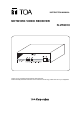
INSTRUCTION MANUAL NETWORK VIDEO RECEIVER N-VR2010 10/100M PoE Thank you for purchasing TOA's Network Video Receiver. Please carefully follow the instructions in this manual to ensure long, trouble-free use of your equipment.
TABLE OF CONTENTS 1. SAFETY PRECAUTIONS ............................................................................... 3 2. LIST OF INCLUDED COMPONENTS AND PARTS ............................... 6 3. GENERAL DESCRIPTION ............................................................................. 6 4. FEATURES .......................................................................................................... 6 5. HANDLING PRECAUTIONS ...................................................................
SAFETY PRECAUTIONS • Before installation or use, be sure to carefully read all the instructions in this section for correct and safe operation. • Be sure to follow all the precautionary instructions in this section, which contain important warnings and/or cautions regarding safety. • Keep this instruction manual handy for future reference.
WARNING Indicates a potentially hazardous situation which could result in death or serious personal injury if ignored or mishandled. When the Unit is in Use • Should the following irregularity be found during use, immediately switch off the power, disconnect the power supply plug from the AC outlet and contact your nearest TOA dealer. Make no further attempt to operate the unit in this condition as this may cause fire or electric shock. · If you detect smoke or a strange smell coming from the unit.
CAUTION Indicates a potentially hazardous situation which could result in moderate or minor personal injury, and/or property damage if ignored or mishandled. When Installing the Unit • Never insert nor remove the power supply plug with wet hands, as an electric shock may result. • When unplugging the power supply cord, be sure to grasp the power supply plug; never pull on the cord itself. The power supply cord may be damaged, possibly causing a fire or electric shock.
2. LIST OF INCLUDED COMPONENTS AND PARTS Check to be sure that the following components and parts are contained in the package: Power conversion cable ...................................................................................................... 1 Network Video Receiver Instruction Manual ........................................................................ 1 3.
5. HANDLING PRECAUTIONS • Do not give the Receiver a great shock or vibration, as this will damage the Receiver. • It is recommended that the Receiver be always used in locations where the ambient temperature ranges from -0°C to +50°C and humidity levels of less than 90% to ensure that no condensation is formed. • To clean, wipe with a dry soft cloth. Never use benzene, thinner or chemically processed towel as the Receiver's plastic or other parts may be deformed or discolored.
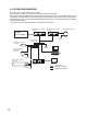
6. SYSTEM CONFIGURATION The connection of a basic system is shown below. The analog CCTV system is comprised of conventional cameras and switchers. When using a PoE-compatible hub, the power supply need not be connected to the N-VT2010 Network Video Transmitter, N-VR2010 Network Video Receiver and N-CC2360 Network Color camera. When using a hub not supporting PoE, power must be independently supplied to each device. Connect the AC mains to N-DR2000 Network Video Recorder.
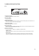
7. NOMENCLATURE AND FUNCTIONS [Front] 10/100M PoE 1 2 3 4 5 6 (1) Initialization Key [INIT] Initializes the setting contents to default conditions. (2) Reset Key [RESET] Restarts the Receiver. (3) Ready Indicator (Green) Lights continuously while the Receiver is operating. The indicator flashes quickly when the Receiver is set to start mode, and flashes slowly during firmware update. (4) Busy Indicator (Yellow) Lights continuously during communications.
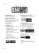
[Rear] 7 8 LINE VOL 9 10 MIC IN VIDEO OUT 11 12 AUDIO ADJ. NC PHANTOM MIC 12V 13 OUT 1 2 24V IN IN ON LINE AUDIO CONTACT OUT IN OUT 1 2 C 1 2 C MAX 0.2A RS485 + CONTACT 14 (7) Audio Input Terminal (-10 dB, 10 kΩ, unbalanced type) Receives line level audio signals. 15 RS485 RS-232C 16 17 (13) 24 V AC/24 V DC Input Terminal (3P) Receives 24 V AC or 24 V DC power. Do not use this terminal when a PoE-compatible hub is used for connection.
8. CONNECTIONS 8.1. Connection example PoE Compatible Switching HUB 8 7 6 5 4 Software Decoder N-SD2000 3 2 1 DC-IN Network Video Receiver N-VR2010 LINE To AC mains VOL VIDEO OUT MIC IN AUDIO ADJ. NC PHANTOM MIC 12V OUT 1 2 24V IN IN LINE AUDIO CONTACT CT OUT ON IN OUT OU 1 2 C 1 2 C Video input MAX 0.
8.2. Monitor connection Connect the Receiver's video output terminal to the monitor's video input terminal using a coaxial cable (75Ω, BNC). 8.3. Network Connection Connect the Receiver to a hub using a straight cable. Use a null modem cable when connecting the Receiver directly to a PC. 8.4. Microphone Connection Connect a microphone using a mini-Jack. When using an electret-condenser microphone, set the 9 V phantom power to ON. 8.5.
8.7. Serial Port [RS-232C] Use a null modem cable such as the YR-S2320 when connecting control terminals of the remote controller to this terminal. No RS-232C connector plug is supplied with the unit. • RS-232C Connector D-sub 9P 1 2 3 4 5 6 7 8 9 No. 1 2 3 4 5 6 7 8 9 Terminal name Unconnected RXD (Reception data) TXD (Transmission data) Unconnected GND Unconnected RTS (Transmission request) CTS (Transmission permission) Unconnected Both the RTS and CTS pins are internally shorted.
8.8. DIP Switch Setting No. 1 2 3 4 1 2 3 4 Terminal name MIC/ LINE PHANTOM AUDIO ADJ NC 1: Selects either microphone level signal or line level signal as the audio input. Set to "MIC" when connecting a microphone, and to "LINE" when connecting other devices. ("LINE" is the default.) 2: Supply voltage is 9 V DC. When supplying the phantom power to the device connected to the audio input terminal, set the MIC/LINE switch to MIC, then set this switch 2 to ON. ("OFF" is the default.
11. SPECIFICATIONS [N-VR2010 CU] Power Source Power Consumption Power Terminal Power Output Video Output Audio Input Audio Output Audio Frequency Response Contact Input Contact Output Serial Port Network Network I/F Network Protocol Video Compression/Resolution Frame Rate Audio Compression/Decompression Audio Sampling Frequency Image Transfer Rate Other Function Operating Temperature Operating Humidity Finish Dimensions Weight * 0 dB = 1V 24 V AC, 50/60 Hz or 24 V DC or PoE (IEEE802.
[N-VR2010 PL] Power Source Power Consumption Power Terminal Power Output Video Output Audio Input Audio Output Audio Frequency Response Contact Input Contact Output Serial Port Network Network I/F Network Protocol Video Compression/Resolution Frame Rate Audio Compression/Decompression Audio Sampling Frequency Image Transfer Rate Other Function Operating Temperature Operating Humidity Finish Dimensions Weight * 0 dB = 1V 24 V AC, 50/60 Hz or 24 V DC or PoE (IEEE802.