
User's Manual

2-5
Chapter 2: UNIT AND SOFTWARE INSTALLATIONS
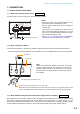
2. CONNECTIONS TO TERMINAL PLUGS
Wire the removable terminal plugs for power input (NX-100 only), audio input and output, and control input
and output as follows:
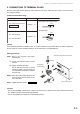
[Cable size and width to strip]
15 mm
7 mm
7 mm
Solid cable and stranded cable
Shielded cable
Application Size Width to Strip
For power supply terminal
For audio terminal
For control terminal
AWG24 – 12
AWG28 – 16
NX-100 only
Caution
Avoid soldering stranded or shielded cable, as contact resistance may increase when the cable is tightened
and the solder is crushed, possibly resulting in an excessive rise in joint temperatures.
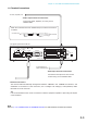
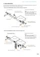
[Wiring procedure]
Step 1. Wiring the supplied removable
terminal plug.
1-1. Loosen the terminal screws to insert
the wire.
1-2. Tighten the terminal screws.
Ensure that the wire does not break
free when pulled. If the wire does pull
free, repeat the connection procedure
from the start.
Step 2. Insert the wired terminal plug into the
corresponding terminal block in the
unit's rear panel.
Step 3. Tighten the fixing screws.
Cautions
• Do not reverse Steps 1 and 2. Poor contact may result if force is applied to the unit's internal circuit board
pins while the terminal screws are being tightened.
• Use an appropriate type screwdriver for terminal plug wiring.
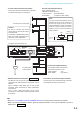
NX-100 only
AUDIO OUTPUT
AUDIO INPUT
H CE
H
C E
MICLINE
VOLUME
INPUT
Removable
terminal plug
1
2
3
NX-100 rear panel
Tighten
Tighten
This figure represents the NX-100.