9000 Series Mixer/Amplifiers RS-232C Protocol Manual Ver.3.
TABLE OF CONTENTS Page# 1. SUMMARY…………………………………………………………………….... 3 2. SERIAL PORT SETTING…………………………………………………….... 3 3. COMMAND CONFIGURATION………………………………………………. 4 4. TRANSMISSION DATA AFTER COMMAND RECEPTION……………….. 4 5. CONTROL COMMAND AND SETTING VALUE……………………………. 5 5.1. Channel Fader Gain……………………………………………………………. 5 5.1.1. Channel Fader Gain - Position setting…………………………………… 5 5.1.2 Channel Fader Gain - Step Up/ Step Down…………………………….…. 7 5.2. Crosspoint Gain………………………………………………………………… 9 5.3.
1. SUMMARY The RS-232C protocol described in this document is designed to be used to control the 9000 Series Amplifier from a PC and/or remote controller. This specification applies to the 9000 Series firmware version 3.13 or later.
• If a next command received contains byte data shorter than the Data length, the previous command is abandoned. 4. TRANSMISSION DATA AFTER COMMAND RECEPTION When normal data is received, the same data as the reception data is to be transmitted. Example: 91H, 03H, 00H, 00H, 00H (Reception data) 91H, 03H, 00H, 00H, 00H (Transmission data) When channel data is received and the data is outside of the range, the data is to be inverted and transmitted.
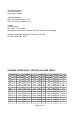
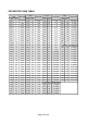
00H: Input channel 01H: Output channel 00H - 07H (Input channel 1 - 8) 00H - 07H (Output channel 1 - 8) Position setting 00 – 7EH (-∞ to +10 dB) See Channel Fader Gain - Position V/S Gain Table on the next page. Example: Setting the fader gain of channel 1 to 0 dB 91H, 03H, 00H, 00H, 6AH CHANNEL FADER GAIN - POSITION V/S GAIN TABLE Position Gain (dB) HEX DEC 00H 0 -∞ 01H 1 -70.0 02H 2 -68.0 03H 3 -66.0 04H 4 -64.0 05H 5 -62.0 06H 6 -60.0 07H 7 -59.0 08H 8 -58.
0DH 0EH 0FH 10H 11H 12H 13H 14H 15H 16H 17H 18H 19H 1AH 1BH 1CH 1DH 1EH 1FH 20H 21H 13 14 15 16 17 18 19 20 21 22 23 24 25 26 27 28 29 30 31 32 33 -53.0 -52.0 -51.0 -50.0 -49.0 -48.0 -47.0 -46.0 -45.0 -44.0 -43.0 -42.0 -41.0 -40.0 -39.5 -39.0 -38.5 -38.0 -37.5 -37.0 -36.5 2FH 30H 31H 32H 33H 34H 35H 36H 37H 38H 39H 3AH 3BH 3CH 3DH 3EH 3FH 40H 41H 42H 43H 47 48 49 50 51 52 53 54 55 56 57 58 59 60 61 62 63 64 65 66 67 -29.5 -29.0 -28.5 -28.0 -27.5 -27.0 -26.5 -26.0 -25.5 -25.0 -24.5 -24.0 -23.5 -23.
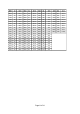
5.1.2 Channel Fader Gain - Step Up/ Step Down Set the input and output channel gain positions by the number of steps. Positions can be varied from the current status by the designated number of steps. One position varies per step. 9000 series Amplifier informs position values changed by commands. Position values are shown in POSITION V/S GAIN TABLE. Values are 1dB step under -40dB, and 2dB step under -60dB. The 9000series Amplifier informs position values changed by Step Up or Down.
CHANNEL FADER GAIN – STEP UP / STEP DOWN TABLE Step Up HEX DEC 41H 65 42H 66 43H 67 44H 68 45H 69 46H 70 47H 71 48H 72 49H 73 4AH 74 4BH 75 4CH 76 4DH 77 4EH 78 4FH 79 50H 80 51H 81 52H 82 53H 83 54H 84 55H 85 56H 86 57H 87 58H 88 59H 89 5AH 90 5BH 91 5CH 92 5DH 93 5EH 94 5FH 95 Gain (dB) +0.5 step +1.0 step +1.5 step +2.0 step +2.5 step +3.0 step +3.5 step +4.0 step +4.5 step +5.0 step +5.5 step +6.0 step +6.5 step +7.0 step +7.5 step +8.0 step +8.5 step +9.0 step +9.5 step +10.0 step +10.5 step +11.
received. This command is enabled when in the mixer mode only. Note: Command cannot be received during power off. 95H, 05H, , , , , 00H: Input channel 00H - 07H (Input channel 1 - 8) 01H: Output channel 00H – 07H (Output channel 1 - 8) 00 - 51H: Gain Position (-∞ to +10.
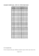
CROSSPOINT GAIN TABLE value Gain (dB) HEX DEC 00H 0 -∞ 01H 1 -70.0 02H 2 -69.0 03H 3 -68.0 04H 4 -67.0 05H 5 -66.0 06H 6 -65.0 07H 7 -64.0 08H 8 -63.0 09H 9 -62.0 0AH 10 -61.0 0BH 11 -60.0 0CH 12 -59.0 0DH 13 -58.0 0EH 14 -57.0 0FH 15 -56.0 10H 16 -55.0 11H 17 -54.0 12H 18 -53.0 13H 19 -52.0 14H 20 -51.0 15H 21 -50.0 16H 22 -49.0 17H 23 -48.0 18H 24 -47.0 19H 25 -46.0 1AH 26 -45.0 1BH 27 -44.0 1CH 28 -43.0 1DH 29 -42.0 1EH 30 -41.0 1FH 31 -40.0 20H 32 -39.0 21H 33 -38.
5.3. Preset Memory Recall Recalls any desired preset memories. 9000Series Amplifier responds with the same data as that received. Note: Settings to be stored in preset memories are referred to as “SCENE” in mixer mode and “EVENT” in matrix mode. Preset Memory Recall command cannot be received during power off.
00H: Input channel 01H: Output channel 00H - 07H (Input channel 1 - 8) 00H - 07H (Output channel 1 - 8) 00H: Channel OFF 01H: Channel ON Example 1: Setting the Input Channel 1 to ON 92H, 03H, 00H, 00H, 01H Example 2: Setting the Input Channel 1 to OFF 92H, 03H, 00H, 00H, 00H 5.5. Power ON/OFF This command performs ON/OFF setting of the power switch of the 9000 Series Amplifier. 9000Series Amplifier responds with the same data as that received.
00H: Input channel 01H: Output channel 00H - 07H (Input channel 1 - 8) 00H - 07H (Output channel 1 - 8) 00H: Bass Gain 01H: Treble Gain 00 - 18H: Gain Position (-12 to +12dB) 21 - 2CH: Position Down (1 –12dB Step Down) 2D - 38H: Position Up (1 – 12dB Step Up) Example 1: Setting the Input Channel 1 Bass Gain fixed value to 0 dB. AAH, 04H, 00H, 00H, 00H, 0CH Example 2: Increasing Input Channel 1 Bass Gain by +3.0 dB step increments.
TONE CONTROL GAIN POSITION TABLE Value Gain (dB) HEX DEC 00H 0 -12.0 01H 1 -11.0 02H 2 -10.0 03H 3 -9.0 04H 4 -8.0 05H 5 -7.0 06H 6 -6.0 07H 7 -5.0 08H 8 -4.0 09H 9 -3.0 0AH 10 -2.0 0BH 11 -1.0 0CH 12 0 Value Step Down HEX DEC 21H 33 -1.0 step 22H 34 -2.0 step 23H 35 -3.0 step 24H 36 -4.0 step 25H 37 -5.0 step 26H 38 -6.0 step 27H 39 -7.0 step 28H 40 -8.0 step 29H 41 -9.0 step 2AH 42 -10.0 step 2BH 43 -11.0 step 2CH 44 -12.0 step Value Gain (dB) HEX DEC 0DH 13 +1.0 0EH 14 +2.0 0FH 15 +3.0 10H 16 +4.
can be valid only when EQ is set to ON. Note: Command cannot be received during power off.
06H 07H 6 7 3 5 EQ-FREQUENCY TABLE Value Freq (Hz) HEX DEC 00H 0 20 01H 1 25 02H 2 31.5 03H 3 40 04H 4 50 05H 5 63 06H 6 80 07H 7 100 08H 8 125 09H 9 160 0AH 10 200 0BH 11 250 0CH 12 315 0DH 13 400 0EH 14 500 0FH 15 630 10H 16 800 Value Freq (Hz) HEX DEC 11H 13 1k 12H 14 1.25k 13H 15 1.6k 14H 16 2k 15H 17 2.5k 16H 18 3.15k 17H 19 4k 18H 20 5k 19H 21 6.3k 1AH 22 8k 1BH 23 10k 1CH 24 12.5k 1DH 25 16k 1EH 26 20k Example: Setting the Input Channel 1’s EQ to ON, Band No.
00H: Loudness OFF 01H: Loudness ON Example: Setting the loudness compensation of Output Channel 2 to ON ABH, 03H, 01H, 01H, 01H 5.9. Filter Settings Perform Filter (HPF/LPF) settings of Input / Output channels. 9000Series Amplifier responds with the same data as the receipt. Note: Command cannot be received during power off.
01H: Low Pass Filter HIGH PASS FILTER Value HPF (Hz) HEX DEC 00H 0 OFF 01H 1 20 02H 2 25 03H 3 31.5 04H 4 40 05H 5 50 06H 6 63 07H 7 80 08H 8 100 09H 9 125 0AH 10 160 0BH 11 200 0CH 12 250 0DH 13 315 0EH 14 400 LOW PASS FILTER TABLE – 01H TABLE – 00H Example: Setting the Input Channel 3’s High Pass Filter to 31.5 Hz. A2H, 04H, 00H, 02H, 00H, 03H 5.10. Input Sensitivity Setting Performs input sensitivity setting of Input channel.
INPUT SENSITIVITY TABLE Value HEX DEC 00H 0 01H 1 02H 2 03H 3 04H 4 Sense (dB) -10 -18 -24 -30 -36 Value HEX DEC 05H 5 06H 6 07H 7 08H 8 Sense (dB) -42 -48 -54 -60 Example: Setting the input sensitivity of Input Channel 5 to –24 dB. ACH, 02H, 04H, 02H 5.11. Phantom Power ON/OFF Setting Sets the phantom power of Input channel to ON or OFF. 9000Series Amplifier responds with the same data as that received. Note: Command cannot be received during power off.
F0H, 03H, 40H, 00H, 00H Response data are provided below. C0H, 09H, , , , , , , , , Example: Responding with the Input Channel 1’s name “INPUT1.” C0H, 09H, 00H, 00H, 49H, 4EH, 50H, 55H, 54H, 31H, 00H Table below shows ASCII codes used for Names.
7. Speaker Preset Setting Recalls speaker EQ preset values for specific TOA model speakers. 9000Series Amplifier responds with the same data as that received. Note: Command cannot be received during power off.
Channel ON/OFF Power ON/OFF Tone control (BASS/ TREBLE) EQ settings - ON/OFF setting - Band No, setting - Gain setting - Q setting - Center frequency setting Loudness compensation 92H, 03H, , , F4H, 01H, AAH, 04H, , , , A1H, 07H, , , ,, , , ABH, 03H, , , A2H, 04H,
9. COMMUNICATION EXAMPLES Command Controller A-9000 Response Channel fader gain Input ch1 Fader gain=0dB 91H, 03H, 00H, 00H, 6AH 91H, 03H, 00H, 00H, 6AH Input ch1 Fader gain 1 step up 93H, 03H, 00H, 00H, 41H 93H, 03H, 00H, 00H, 6CH (Amplifier response of +1dB Input Channel 1 fader gain after command.
Input ch1 Insense -24dB ACH, 02H, 00H, 02H ACH, 02H, 00H, 02H Speaker preset setting Output ch2 SpPreset F-122 ADH, 02H, 01H, 01H ADH, 02H, 01H, 01H Phantom power setting Input ch3 Phantom ON 87H, 02H, 02H, 01H 87H, 02H, 02H, 01H Channel name recall Input ch1 Name “INPUT1” F0H, 03H, 40H, 00H, 00H Page 24 of 24 C0H, 09H, 00H, 00H, 49H, 4EH, 50H, 55H, 54H, 31H, 00H