OPERATING INSTRUCTIONS LINE ARRAY SPEAKER SR-A12L, SR-A12S, SR-A18B, SR-A12LWP, SR-A12SWP RIGGING FRAME SR-RF12, SR-RF12WP TILT JOINT PLATE SR-TP12 Note that casters must be prepared separately. Thank you for purchasing TOA’s Line Array speaker system, Rigging Frame and Tilt Joint Frame. Please carefully follow the instructions in this manual to ensure long, trouble-free use of your equipment.
TABLE OF CONTENTS 1. SAFETY PRECAUTIONS ............................................................................... 3 2. GENERAL DESCRIPTION ............................................................................. 5 3. FEATURES .......................................................................................................... 5 4. DIMENSIONS ...................................................................................................... 5 5. INPUT CONNECTORS ...........................
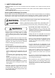
1. SAFETY PRECAUTIONS • Before installation or use, be sure to carefully read all the instructions in this section for correct and safe operation. • Be sure to follow all the precautionary instructions in this section, which contain important warnings and/or cautions regarding safety. • After reading, keep this manual handy for future reference.
CAUTION • When unpacking or moving the unit, be sure to handle it with two or more persons. Falling or dropping the unit may cause personal injury and/or property damage. • Avoid placing the unit in a doorway or other high traffic area as people may trip on the equipment and cords, or be injured by falling objects. • Avoid touching the unit's sharp metal edge to prevent injury. 4 • Do not operate the unit for an extended period of time with the sound distorting.
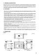
2. GENERAL DESCRIPTION TOA’s SR-A series Line Array speaker employ unique wave front control technology to create a sound field with high sound clarity and uniform sound pressure. The lineup features types with vertical directivity angles of 5 degrees and 15 degrees, as well as subwoofers.
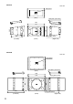
SR-A12S Unit: mm Input panel (Rear) Joint plate (accessory) Flying plate (Front) 399 433 15˚ 282 740 716 467 Flying plate (Rear) (Left Side) (Right side) (Front) SR-A18B Unit: mm Input panel Joint plate (accessory) (Rear) 740 698 (Left Side) 6 Flying plate (Front) 540 573 716 Flying plate (Rear) (Front) (Right side)
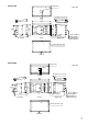
SR-A12LWP Input panel Unit: mm Joint plate (accessory) (Rear) 740 400 Flying plate (Front) 433 5˚ 360 716 469 Flying plate (Rear) (Left Side) (Front) (Right side) Green LOW (+) Black LOW (-) Red HIGH (+) White HIGH (-) Air Hole (Bottom only) (Bottom) SR-A12SWP Input panel Unit: mm Joint plate (accessory) (Rear) 740 716 399 433 15˚ 282 Flying plate (Front) 467 (Left Side) Flying plate (Rear) (Front) (Right side) Green LOW (+) Black LOW (-) Red HIGH (+) White HIGH (-) Air Hole
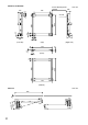
SR-RF12, SR-RF12WP Caster Mounting Plate 16-M10 164 35 595 Unit: mm 105 71 95 180 71 95 140 (Left side) (Top) 716 4.
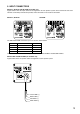
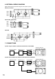
5. INPUT CONNECTORS SR-A12L, SR-A12S and SR-A18B (for Indoor use) Figures below show the input connector arrangements of each speaker system. Since connector and screw terminal are internally connected in parallel, either connector can be used for connection. SR-A12L, SR-A12S SR-A18B The NEUTRIK NL4MP connector’s pins are wired as shown below. Pin No.
6. INTERNAL WIRING DIAGRAM Figures below show the internal wirings of each speaker system. SR-A12L, SR-A12S LOW + 1+ LOW - 1+ 2- 1- 2- 1- HIGH + 2+ HIGH - 2+ SR-A12LWP, SR-A12SWP LOW + Green LOW - Black HIGH + Red HIGH - White Speaker cable SR-A18B INPUT + INPUT - 1+ 2- 1+ 2- 1- 1- THROUGH THROUGH 2+ 2+ 7.
8. DIGITAL PROCESSOR SETTINGS Recommended setting parameters are as follows. System using the SR-A12L, SR-A12S, SR-A12LWP or SR-A12SWP Channel Gain (dB) Polarity LOW 0 Normal HIGH 0 Inverse Filter Q Delay (msec) 40 0.900 0.708 TYPE Freq.. (Hz) HPF (12 dB) Gain (dB) LPF (12 dB) 1.0k 0.707 LPF (12 dB) 1.0k 0.707 PEQ 300 -5.0 2.549 PEQ 530 -4.5 2.549 HPF (12 dB) 1.2k 0.707 PEQ 2.5k -10.0 1.011 PEQ 5.0k -2.0 1.414 PEQ 14.0k 9.0 1.
9. FLYING 9.1. General Description Use the SR-RF12(WP) Rigging Frame for flying the Line Array speaker. With the use of the SR-RF12(WP), up to 8 Line Array speakers can be arranged in flying configuration. The SR-A18B Subwoofer system is counted as 1.5 pieces. When joining two or more speakers, or joining the rigging frame and the speaker, use the Joint Plate supplied with the speaker. Basic flying system is shown below.
This flying system is made up of four SR-A12L speakers, two SR-A12S speakers, and one SR-A18B speaker. To transmit sound over long distances, the four SR-A12Ls are given overlapping angles of 4, 2, and 1 degree, resulting in a total vertical directivity angle of 43 degrees. The overlapping angle can be adjusted by means of the Joint Plates used to join the speakers. The horizontal directivity angle is fixed at 90 degrees.
9.3. Joining the Enclosure to the Rigging Frame Flying Plates are mounted at both the front and rear of the enclosure’s sides. Follow the procedure below to mount the enclosure to the Rigging Frame, as shown in the assembly diagrams. Fix a supplied Joint Plate securely to the left side of the Rigging Frame and another to the right side of the enclosure, each using 4 supplied bolts with plain washers and spring washers.
9.4. Joining Enclosures Use the supplied Joint Plate to join the enclosures by way of the enclosure's flying plate. As shown in the figure, mount a Joint Plate securely to the upper enclosure's lower left side, using 4 supplied bolts with plain washers and spring washers. Similarly, attach another Joint Plate to the lower enclosure's upper right side. Joint Plate Joint Plate Join the enclosures securely, using 4 supplied bolts with plain washers and spring washers on each side.
9.5. Notes on Flying WARNING • Check to confirm that the suspension wires, belts, construction of the ceiling, etc are strong enough to withstand the speaker load. • Tighten each joint bolt to 300-350 kg·cm of torque securely.Be sure to use the joint bolts supplied with the speaker and the Rigging Frame. • Up to 8 Line Array speakers can be arranged in flying configuration per one Rigging Frame. The Subwoofer is counted as 1.5 pieces. No more than 8 speakers can be arranged in flying configuration.
Notes on Outdoor Installation WARNING • In case of outdoor installation, follow the notes mentioned below. • Only the SR-A12SWP or SR-A12LWP Line Array speaker can be installed outdoors. There is no Subwoofer available to be installed outdoors. • WP type speaker features the water protection construction (IPX4), however install it under roofs, eaves, or other locations not directly exposed to rain or snow.
10. STACKING 10.1. General Description Line Array speakers can be stacked using the SR-RF12 Rigging Frame. Up to 5.5 speakers can be stacked, counting each Line Array speaker as 1 piece and each SR-A18B Subwoofer as 1.5 pieces. Shown below is a basic stacked system. Note that casters must be prepared separately. SR-A12L Joint Plate SR-A18B Rigging Frame Caster (required by the user) This stacking system is made up of four SR-A12L speakers, and one SR-A18B speaker.
10.3. Mounting the Enclosure to the Rigging Frame Flying Plates are mounted to the front and rear of the enclosure’s sides. Follow the procedures below to mount the enclosure to the Rigging Frame, as shown in the assembly diagrams. Fix a supplied Joint Plate securely to the right side of the Rigging Frame, and another Joint Plate to the left side of the enclosure, each using 4 supplied bolts with plain washers and spring washers.
10.4. Joining Enclosures For joining enclosures, refer to “9 Flying, 9-4. Joining Enclosures”. 10.5. Notes on Stacking • Prepare casters and caster mounting bolts separately, as the Rigging Frame’s leg. • When stacked, the Line Array speaker’s front or rear deviation from the Rigging Frame must be within 10cm. Also, whenever possible, select mounting plate positions that allow the system’s center of gravity to be situated near the center of the Rigging Frame.
10.6. Tilting the Enclosure Downward The lower Line Array speaker, excluding the subwoofer, can be tilted downward with the addition of SR-TP12 Tilt Joint Plates. SR-TP12 Tilt Joint Plates make it possible to set wider angles than can be achieved using the supplied Joint Plates. Replace the lowermost Line Array speaker’s Joint Plates with the Tilt Joint Plates, then assemble the system.
Typical stacking example using the tilt joint plate SR-A18B x1, SR-A12S x1, SR-A12L x3 SR-A12L Vertical facing angle: 0 degree - 15 degrees SR-A12S SR-A18 Vertical facing angle: 0 degree - 15 degrees (Left side) (Right side) SR-A12S x1, SR-A12L x4 SR-A12L Vertical facing angle: 10 degrees - 15 degrees (Left side) WARNING 22 SR-A12S Vertical facing angle: 10 degrees - 15 degrees (Right side) Do not use the Tilt Joint Plate for joining Line Array speakers (excluding the sub-woofer), for joining
11.
SR-A18B Model Enclosure Power Handling Capacity Rated Impedance Sensitivity Frequency Response Crossover Frequency Speaker Component (low) Input connectors Finish Dimensions Weight Accessories SR-A18B Bass-reflex type Continuous program: 720 W 8Ω 95 dB (1 W, 1 m) 40 – 400 Hz (when using the optional DP-0206) 80 Hz (when using the optional DP-0206) 46 cm Cone type M5 Screw terminal, distance between barriers: 12.