B TA 1400 USER MANUAL
1 CONTENTS 1 2 3 CONTENTS ........................................................................................................................1 APPROVALS ......................................................................................................................2 WARNINGS ........................................................................................................................2 3.1 Explanation of graphical symbols ...............................................................
2 APPROVALS This equipment conforms to the requirements of the EMC directive 89/336/EEC, amended by 92/31/EEC and 93/68/EEC and the requirements of the Low Voltage Directive 73/23/EEC, amended by 93/68/EEC. Standard Applied EMC Emission EN55103-1, E3 EMC Immunity EN55103-2, E3, with S/N below 1% at normal operation level. Electrical Safety EN60065, Class 3 WARNINGS 3.
10. Do not use this amplifier if the power cord is broken or frayed. Protect the power cord from being walked upon or pinched particularly at the plugs and the point where it exits from the apparatus. 11. Only use accessories specified by the manufacturer. ! 12. The unit is intended to use in a 19” rack. Follow the mounting instructions. When a rack on wheels is used, use caution when moving the loaded rack to avoid injury from tipping over. 13.
If this equipment does cause harmful interference to radio or television reception, which can be determined by turning the equipment on and off, the user is encouraged to try to correct the interference by one or more of the following measures: • • • • • Reorient or relocate the antenna. Increase the separation between the equipment and receiver. Connect the equipment into an outlet on a circuit different from that to which the receiver is connected.
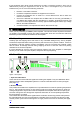
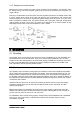
3. Clip/limit indicator This indicator signals when the amplifier output is clipping or limiting. It has two different indication states: If the clip limiter is engaged, it has a short time constant and it illuminates briefly. (See page 13). If the clip limiter is not engaged, it has an increased time constant and it illuminates for a longer period. 4. Signal present indicator. Illuminates at –40dB below full output signal. 5.
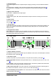
8. Gain switch channel A. Three of the switches in the DIP-switch selects the maximum gain of the channel to be either 20, 23, 26, 29, 32, 36, 39 or 41 dB. (See page 6). 9. AC power cable. WARNING! A label just below the mains cable on the rear of the amplifier indicates the AC mains voltage, for which the amplifier is wired. Connect the power cable only to the AC source referred to on the label. ! 5 REAR PANEL FEATURES 5.
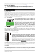
5.2 Link switch The Link switch located on the rear panel (the central DIP-switch) is for changing the operation mode of the amplifier (see below, section 5.3). 5.3 Operation modes 5.3.1 Stereo mode In this mode, both channels operate independently of each other. This is used for all 2-channel modes, such as stereo and bi-amping. Set the two center switches to off position for the stereo mode. The level attenuators on the front panel will control the respective channels levels.
5.3.5 Bridge mono mode features Bridged mono mode combines the power of both channels into one speaker. This results in twice the voltage swing, four times the peak power and just less than three times the full power of a single channel. One way to understand the load and power from the amplifier’s perspective in bridged mode is that it is zero voltage at the center of the voice-coil winding.
6.3 Operating voltage WARNING! A label just below the mains cable on the rear of the amplifier indicates the AC mains voltage, for which the amplifier is wired. Connect the power cable only to the AC source referred to on the label. The warranty will not cover damage caused by connecting to the wrong type of AC mains.
clip and is therefore the highest power level one can obtain without completely obliterating the program. Last, the "normal operating power", as defined by the safety standard IEC 65/ANSI/UL 6500 and used by a majority of safety agencies. The normal operating power is measured using pink noise, with an average output power equal to 1/8 of full power. The one eighth of the total power is as loud as you can play music while making some attempt to avoid obvious clipping.
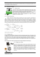
Within the Neutrik® Combojack there is a ¼”(6.3mm) phone jack, which is wired in parallel with the XLR. TIP RING SLEEVE HOT COLD SHIELD/GROUND Figure 6. ¼” TRS plug The input impedance is high enough (20 kohms balanced) to allow ”daisy-chaining”, or multiple parallel input connections. The headroom of the input circuits is also high enough to accept the maximum output level from virtually any low-level signal source. Balanced signals are less sensitive to AC hum and radio interference.
7.2 Connecting speakers Speaker connections are made via the two Neutrik® NL4FC Speakon connectors. The Speakon connector is designed for high power speaker connections. It assures the correct polarity, it locks in place and prevents from shock hazard. They are wired in the following manner: The right jack, Channel A, has both channel A and B outputs, so it’s useful for bridging and bi-amp operation (see bridged mono operation on page 7). The left Speakon, Channel B, carries only the channel B output.
8.2 Powering up – Soft start When you power up the amplifier it takes a couple of seconds to check its circuits. This is known as the "soft-start" or "slow-start" sequence. The fans then blow at high speed before going into "idle" and the two bottom green LED’s illuminate to show the amplifier is operational. 8.3 Input attenuators The two input level attenuators on the front panel adjust the signal level for their respective amplifier channel in all modes.
9.1.2 Thermal protection If the amplifier is driven very hard into a low impedance load, the cooling fans will run at high speed. If the causing conditions continue, the Temperature indicator(s) will illuminate indicating that the amplifier is about to go into thermal shutdown. After five seconds the amplifier will go into thermal protection by muting the input signal. After 15-20 seconds the amplifier will have cooled down enough for the amplifier to come out of shutdown and operate as normal.
mistake to a 3 phase supply, an internal non-resetable fuse or resistor may have blown. Then return the amplifier to your supplier for service. Fault: The amplifier does not respond even after checking above items. In the unlikely event of on a non-user rectifiable fault, return the amplifier to your supplier or an approved service centre. Tannoy cannot be held responsible for damage or injury as a result of the top cover being removed.