INTERCOM SYSTEM TOA EXES-5OOO INTERCOM SYSTEM TROUBLE SHOOTING GUIDE TOA ELECTRIC CO., LTD.
8. TROUBLE SHOOTING GUIDE Repairing of the EXES-5000 system is basically done by replacing defective units with good ones. The system's faults in an installation can be divided into the following categories. 1. Faults in an exchange 2. Faults in a station 3. Cable faults To make system repairing easier, find which category is involved, then refer to the chart below for assistance in fault finding. All stations do not operate. Same symptom in every station. Fault in an exchange.
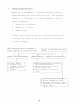
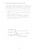
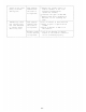
EXES-5000 SYSTEM CHECK FLOW CHART START Table 1: DIP switch on CPU correctly set ? Set DIP switch according to Inst. Back-up battery on CPU connected ? Plug the Jack into Pin A. Program switch on CPU off ? Program switch off P54 Fig. 1 P56 Fig. 2 Power switch on Proper voltages at each output power terminal? (tabl 1) Disconnect DC power connection and check No.
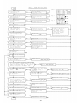
8-1. FAULT IN EXCHANGE Before power supply check, confirm the following three points to eliminate elementary faults: 1. 2. 3. Is voltage selector set correctly? Is AC power supplied? Is power switch O N ? Start checking after disconnecting all wiring connected to DC output of the power supply unit. SYMPTON CHECK-ITEM Exchange does not operate. All DC output voltages are correct. Over-current flows into one of plug-in units. All or one of DC output voltages are not correct.
8-2. HOW TO FIND SHORT BETWEEN T-LINE AND R-LINE If the shorted condition between T-line and R-line is not corrected for a long time, it may burn out the guard resistor (330 , 1/2W) on the LMU board. Therefore, find the shorted line according to the following procedure: 1. 2. 3. Turn off the privacy switch on all stations in the system. Turn on the power switch of the system for several seconds, then, turn it off. Watch the lamps on the LMU panels.
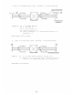
1. One of transmitting lines (T-Line) is disconnected. Station EXCHANGE 1-1 A can make dialing. Symptom 1-2 1-3 1-4 1-5 LMU Lamps 2. A can hear B . B can not hear A . Noise is heard at B . Noise increases at B when Press-To-Talk bar is pressed at A . Normal One of receiving lines (R-Line) is disconnected. EXCHANGE Sympton: 2-1 A can make dialing without dialing tone. 2-2 When B dials A , busy tone or dial tone will be heard at B immediately after the calling tone.
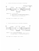
3. T-Line and R-Line are shorted or mixed up. Shorted or mixed up EXCHANGE Symptom 3-1 A can not dial. 3-2 Conversation is impossible between stations. 3-3 When B dials A , noise will be heard at B immediately after the calling tone. LMU Lamps 4. Brighter than normal. T-Line and R-Line are connected conversely. Sympton: 4-1 A can not make dialing. 4-2 Conversation is impossible between stations. 4-3 When B dials A , noise will be heard at B . LMU Lamps Brighter than normal.
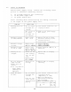
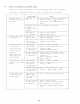
-3. FAULT IN SPECIFIC STATION ONLY Find the cause according to the following table if the fault lies with a specific station only, not with all stations. CAUSE CHECK-ITEM Dialing can not be made at privacy off mode. LMU Lamp is off. Disconnection of both T & R-Lines. Guard resistor 330 on LMU is burned out due to T & R-Lines short. Specific Lamp on LMU is brighter than normal. T & R-Lines are shorted. LMU Lamp is on in normal. Fault in the station. (Replace PCB board.
Sound of the other party is broken during call. Same symptom remains even the station is replaced. Adjust the volume control of station speaker if the room produces reverberation. (Lower the volume.) Increase the gain of MIC AMP. Replace PCB after checking if MIC unit is not touching its case. Immediately after the calling tone, the line switches to cancel, busy, dial tone, etc. Same symptom remains even the station is replaced. One of R-Lines is disconnected. Fault in photo coupler PC-504 on LMU.
8-4. SPEECH AND FUNCTION TEST 1. Speech Test After completing the wiring check and the power supply and exchange test according to the system flow chart, the speech test for each station can then take place. IMPORTANT NOTE Before testing, all programming (Secretary transfer, Master/Substation, Executive Priority Function) must be cleared from station No.200 by turning on the PRO- GRAM switch of the CPU, or the speech test can not proceed correctly.
2. Function Test Check all employed functions with a few stations near the exchange. Check "User Programmable Functions" at stations involved after the programming from station 200. Secretary Transfer: Is transfer made correctly with the privacy switch on at the executive station. Master/Substation : Touch dial at substation can call its master station. Executive Priority: Is this function operated at stations involved. and Use all number keys including , PressTo-Talk bar, Vol.
MEMO
MEMO
TOA ELECTRIC CO., LTD.