
User's Manual

4
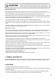
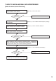
4. HANDLING PRECAUTIONS
• Make sure that the power switch is switched OFF after use.
• When mounting in an equipment rack, select the position which does not expose the unit to high
temperature.
• When installing, keep the unit as far away as possible from fluorescent lamps, digital equipment, personal
computers, and other equipment which generate high frequency noise.
• Only the same bank wireless systems can be used in the same location. Avoid using the systems in
combination with those of different banks because interference or noise could be generated.
• Wireless tuners to be installed in the same location must differ from each other in channel number. Setting
them for the same channel number could result in noise. Wireless microphones must be identical to wireless
tuners in both bank and channel numbers.
• When using two or more wireless microphones, keep them at least 50 cm away from each other to avoid
malfunctions or noise.
• Keep the wireless microphone at least 3 m away from the receiving antenna. Using the microphone in close
proximity to the antenna could result in malfunctions or noise.
• Be sure to connect at least two receiving antennas (one each for Channels A and B).
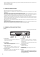
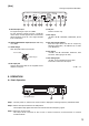
5. NOMENCLATURE AND FUNCTIONS
[Front]
AF PEAK BTT ANT
AB
VOLUME
010
UP
SET
DOWN
POWER
UHF WIRELESS
DIVERSITY WIRELESS TUNER WT-5800
12 5 6 7 83 4
1. Power switch
Press this switch to turn the power on, and press it
again to turn off the power.
2. AF peak lamp
Lights when the output level reaches the point of
about 3 dB below the clipping level.
3. Battery alarm lamp
Lights when the battery voltage in the
corresponding wireless microphone becomes low.
4. Reception lamps
Either lamp of A (left) or B (right) lights yellow
when the tuner receives a radio signal.
5. LCD screen
Displays the receiving frequency, and RF/AF
levels in 6 steps when the unit is in normal
operating state.
In setting mode, the screen displays the setting
items and their contents.
6. Volume control
Adjusts an output level.
7. Up/Down keys
Select the setting items displayed on the screen.
8. Set key
Brings the unit in setting mode when pressed in
normal operating state. In setting mode, pressing
the Set key determines the selected setting item
and registers its contents.
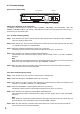
This figure represents WT-5800.
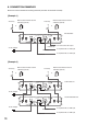
• Antenna distribution outputs (WT-5800 only) and audio cascade inputs facilitate connection of another unit to
build a dual-channel system.
• Compact and high reliability