
User's Manual

5
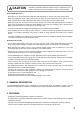
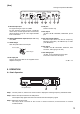
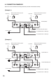
[Rear]
ANT A
OUT IN
ANT B DC IN I/O MIX INOUTPUT 600 10k
OUTIN
UNBALANCED UNBALANCED
BALANCED
-
20dBV
-
20dBV
LEVEL
LINE
-
60dBV
MIC
12 270mAmax
18V
HOT
HOT
COLD
12
3
9 10 91011 12 13 14 15 16
17
9. Antenna input A, B
For signal routing A. Input: 75 Ω, BNC
For the wireless system covering a relatively
narrow area, use the supplied two rod antennas,
which should be set up at a 45° angle outwards
from a vertical line.
10. Antenna distribution output A, B (WT-5800 only)
75 Ω, BNC
11. Cable hanger
Hook the power cable onto this part.
12. DC input jack
Connect the power cable of the supplied AC-DC
adapter to this jack.
13. I/O port
Used for service only.
14. AF output
–20 dB*/– 60 dB* selectable, unbalanced, phone
jack.
15. AF output level selector
Sets the output level from the AF outputs by
selecting either MIC (– 60 dB*/600 Ω) or LINE
(–20 dB*/600 Ω).
16. AF output
–20 dB*/– 60 dB* selectable, balanced, XLR
connector, male type (pin #2: Hot)
17. AF mixing input
–20 dB*, 10 kΩ, unbalanced, phone jack.
Connects to other unit's AF output.
* 0 dB = 1 V
Cable hanger
Power cable
This figure represents WT-5800.
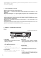
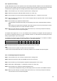
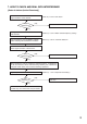
6. OPERATION
6.1. Basic Operation
Step 1. Turn the power on, and the LCD screen comes to display the receiving frequency and RF/AF levels.
Step 2. Set the microphone switch to the ON position.
The reception lamp lights when the tuner receives the same frequency signal.
Step 3. Adjust the volume control.
The output level increases as the control is rotated clockwise, and decreases as rotated
counterclockwise.
AF PEAK BTT ANT
AB
VOLUME
010
UP
SET
DOWN
POWER
UHF WIRELESS
DIVERSITY WIRELESS TUNER WT-5800
13
Reception lamps