
User's Manual


4
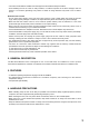
5. NOMENCLATURE AND FUNCTIONS
[Front]
[Rear]
12 25 6 7 8 1043 9
11 12 13 14 15
1. Power switch
Press this switch to turn the power on, and press it
again to turn off the power.
2. Rod antennas
Raise both antennas at 45° outwards from a
vertical line.
When carrying the unit, be sure to fold down both
antennas to prevent them from break.
3. Reception lamps
Either lamp of A (left) or B (right) lights yellow
when the tuner receives a radio signal.
4. Battery alarm lamp
Lights when the battery voltage in the
corresponding wireless microphone becomes low.
5. AF peak lamp
Lights red when the tuner output level reaches the
point about 3 dB below the clipping level.
6. Squelch control
Adjusts the squelch level.
7. RF check button
Switches off the squelch for monitoring the
receiving frequency.
8. Channel number display
Indicates the current channel number in normal
state.
In setting mode, the indicated channel number
flashes until registered.
9. Channel setting keys (SET and NEXT keys)
Used to select the receiving channel (frequency).
(The tuner frequency must be identical to that of
the microphone.)
10. Volume control
Adjusts the output level.
11. I/O port
Used for service only.
12. DC input jack
Connect the power cable of the supplied AC-DC
adapter to this jack.
13. AF output
Balanced XLR jack, male type (Pin #2: Hot)
14. AF output
Unbalanced phone jack
15. AF mixing input (unbalanced)
Connects to other unit's AF output.
Input level: –20 dB, 10 kΩ (0 dB = 1 V)