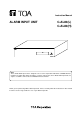
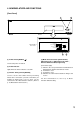
Instruction Manual ALARM INPUT UNIT C-AL80(L) C-AL80(H) POWER ON OFF Note The C-AL80 Alarm Input Unit is designed to be used in conjunction with TOA's C-RM500 Remote Controller to enable their alarm operations or remote control. Thus, the C-AL80 Alarm Input Unit can only be used while connected to a C-RM500 Remote Controller. Thank you for purchasing TOA's Alarm Input Unit. Please carefully follow the instructions in this manual in order to ensure long, trouble-free use of your Alarm Input Unit.
TABLE OF CONTENTS 1. SAFETY PRECAUTIONS ................................................................................ 3 2. GENERAL DESCRIPTION ............................................................................. 4 3. HANDLING PRECAUTIONS .......................................................................... 4 4. NOMENCLATURE AND FUNCTIONS Front Panel ............................................................................................................... 5 Rear Panel ..................
1. SAFETY PRECAUTIONS • Before installation or use, be sure to carefully read all the instructions in this section in order to ensure long, trouble-free operation. • Be sure to follow all the precautionary instructions in this section, which contain important warnings regarding safety. • After reading, keep this manual handy for future reference.
CAUTION Indicates a potentially hazardous situation which could result in moderate or minor personal injury, and/or property damage if ignored or mishandled. When Installing the Alarm Input Unit • Never insert nor remove the power supply plug with wet hands, as an electric shock may result. • When unplugging the power supply cord, be sure to grasp the power supply plug; never pull on the cord itself. The power supply cord may be damaged, possibly causing a fire or electric shock.
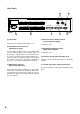
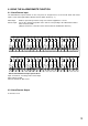
4. NOMENCLATURE AND FUNCTIONS [Front Panel] 1 2 POWER ON OFF Cover The inside of the cover LEVEL REMOTE OFF ABBREVIATION No.9001 REMOTE ALARM ABBREVIATION No.1 REMOTE ON EDGE ON 1 2 3 4 1 2 3 4 4 (1) Power Switch [ON/OFF ] Used to turn power on and off. (2) Power Indicator Lights when the Power switch is set to ON. (3) Unit No. Setting Switch [ON/OFF] Used to set the unit number when performing master/slave connections (cascade connections) for multiple C-AL80 units.
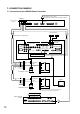
[Rear Panel] 11 7 ALARM/ / REMOTE IN MASTER / SLAVE OFF ON TERMINATION CAMERA SELECT OUT 5 6 (5) Power Inlet 8 ALARM / REMOTE OUT RS-232C 9 10 (8) Camera Selection Output Terminal [Camera Selection Output] Connects to the supplied power supply cord. It cannot be used. (6) Alarm/Remote Input Terminal [Alarm/Remote Input] Use the Mode Selection switch (4) to perform input function settings.
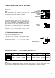
5. MODE SELECTION SWITCH SETTINGS Perform settings of Alarm/Remote input, and alarm intervals here. Note Make sure that the Power switch is set to OFF when setting each Mode Selection switch. The Mode switch is not correctly set if the Power switch is set to ON. 5.1. Alarm/Remote Input Settings LEVEL REMOTE OFF ABBREVIATION No.9001 REMOTE ALARM ABBREVIATION No.1 REMOTE ON EDGE Using Mode Selection switch 1, select either "Alarm" or "Remote" for Alarm/Remote input.
5.3. Alarm/Remote Output Settings It cannot be used. Please fix to the "Remote OFF" (Factory-preset position: "Remote OFF") REMOTE OFF 3 REMOTE ON 5.4. Alarm Interval Settings Set the alarm time interval to "Edge" or "Level" with Model Selection switch 4. Selecting "Edge" causes the system to operate on alarm for a specified period of time (Alarm Interval set by the Remote Controller) when an alarm signal is received.
6. USING THE ALARM/REMOTE FUNCTION 6.1. Alarm/Remote Input The Alarm/Remote input terminals on the rear panel are designed to be used for both alarm and remote inputs. Select either input with the Mode Selection switch. (Refer to p. 7.) Alarm input: Remote input: 1 17 2 18 Enables spot alarm operations using such external equipment as sensors. Selects the channel and position of the camera corresponding to the abbreviation number when shorted to GND.
7. CONNECTION EXAMPLE 7.1.
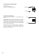
7.2. Master/Slave Connection Example For details about unit number settings, etc., refer to p. 19; Master/Slave Connections. RS-485 Termination switch (11) Unit Number Setting switch (3) C-AL80 Alarm Input Unit Master Unit ON 1 2 3 4 OFF ON Termination OFF Unit No. RS-485 Termination switch (11) Unit Number Setting switch (3) OFF Slave Unit 1 ON Termination ON 1 2 3 4 OFF Unit No.
8. MASTER/SLAVE CONNECTIONS An entire system can have up to 256 Alarm/Remote inputs through master/slave connections (cascade connections) of up to 8 C-AL80 Units. 8.1 Unit Number Settings Be sure to set the unit number when making master/slave connections. Because each component is factory-preset to the unit number for individual use (same setting as the master unit), change the number when making a master/slave connection.
• Master/Slave Terminal Cable Type Use the supplied DIN plug and the twisted pair cable with plug for connection between the Master/Slave terminals. Refer to the figure shown below and note the correct polarity when making the connection. Pin No. 1 – Pin No. 1 Pin No. 3 – Pin No. 3 Control signal (positive) Control signal (negative) Do not connect pins Nos. 2, 4, and 5.
9. RACK MOUNTING When mounting the C-AL80 Unit in an equipment rack, remove 4 plastic feet on the bottom plate and attach an optional MB-23B mounting bracket. C-AL80 AR 5x12 S-tight screw (supplied with MB-23B) AR M UN IT C- AL 80 M4x12 binding head screw (supplied with MB-23B) supplied with MB-23B Fiber washer (supplied with MB-23B) Note • Use the Alarm Input Unit in locations with ambient temperature of between +0°C and +40°C.
10. IF A FAILURE IS DETECTED... (TROUBLESHOOTING) Symptom Cause Cannot switch power on. • The supplied AC cord is not connected to the C-AL80 Unit's Power inlet and AC outlet. Cannot activate an alarm. • • • • The C-AL80 Unit is not correctly connected to the Remote Controller. The C-AL80 Unit's Mode Selection switch is not set to "Alarm." [Sensor Alarm] is not set to "ON" on the Remote Controller menu. Abbreviation number corresponding to the Remote Controller is not registered.
11. SPECIFICATIONS [C-AL80(L), C-AL80(H)] Power Source (L) : AC110 – 120 V, 50/60 Hz (H) : AC220 – 240 V, 50/60 Hz Power Consumption 3 W(60 mA) 6 W(60 mA) Alarm/ Remote Input 32 channels, no-voltage make contact input, open voltage : 5V DC, short-circuit current : max. 5 mA, M3 screw terminal, distance between barriers : 7.