OPERATING INSTRUCTIONS OUTDOOR CAMERA HOUSING C-CH100 C-CH100FH Please follow the instructions in this manual to obtain the optimum results from this unit. We also recommend that you keep this manual handy for future reference.
TABLE OF CONTENTS 1. SAFETY PRECAUTIONS ........................................................................................... 3 2. GENERAL DESCRIPTION ......................................................................................... 4 3. HANDLING PRECAUTIONS ..................................................................................... 4 4. NOMENCLATURE ........................................................................................................ 4 5. INSTALLATION EXAMPLES 5.
1. SAFETY PRECAUTIONS • Be sure to read the instructions in this section carefully before use. • Make sure to observe the instructions in this manual as the conventions of safety symbols and messages regarded as very important precautions are included. • We also recommend you keep this instruction manual handy for future reference.
2. GENERAL DESCRIPTION TOA's C-CH100 and C-CH100FH are rainproof outdoor camera housings to protect video cameras and their lenses from a direct sunlight, rain and wind. The C-CH100FH comes with a heater and fan. 3. HANDLING PRECAUTIONS • Avoid applying extremely strong force to the unit when opening or closing the camera housing cover. Frequent application of force may cause damage to a stay function.
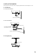
. INSTALLATION EXAMPLES The housing can be mounted to the wall or ceiling using optional brackets and mounting hole ⑨ or ⑩. 5.1. Wall Mounting 5.1.1. Fixed camera orientation C-BC100K (option) 5.1.2. Use of Pan/Tilt Drive C-PH200 (option) Use suitable mounting holes in the pan/tilt drive to mount. C-BC200K (option) 5.2.
. OPENING AND CLOSING THE CAMERA HOUSING COVER (SUNSHADE) ⑦ Lock release button Lock Close Push ② Cover (Sunshade) ⑦ Lock release button Lock Close Close ⑧ Stay Lock ⑧ Stay Lock Lock Close ③ Latch catch (with key hole) Close ① Base Caution ④ Hook Take care when handling the sharp edges of the metal case, as injuries to the hand could result. To prevent potential harm to fingers when closing the cover, do not operate both stays simultaneously.
6.2. Hanging Installation Procedure 6.2.1. Opening the cover 1. While holding the bottom of the camera housing base ① with one hand, undo the cover latches ③ and slowly lower the base to its full stop. Note: Failure to hold the base when undoing the latches could result in the base falling suddenly and possibly damaging the camera. 2. Move the sliding cover stays ⑧ outward until they click into their locking positions. 6.2.2. Closing the cover 1.
. CONNECTIONS Caution Keep wires as far as possible from a heater (C-CH100FH only) because fires or electric shock could result. To avoid burns, do not touch a heater (C-CH100FH only). Heater (C-CH100FH only) Orientation of lens ① Base Be sure to use an optional 24 VAC adapter (CC-5941B) for 24 VAC power. Failure to do this could cause fires. Note: Power must be switched on after connection completion.
8.2. When Using the Outdoor Pan/Tilt Drive C-PH200 Modify the housing cable supplied with the pan/tilt drive as follows. Push the cable into the inside through the cord entry bushing ⑫ located in the bottom panel of the base ①, then make connection as shown in the figure below or in the figure on page 10. Purpose of use Wire No. Connection method Wire color 1 AC power (common) Green 2 AC power Yellow Connects to the 24 VAC terminal (refer to the figure on page 8) of the power input terminal block.
8.2.3. Connection when using the C-CH100FH in combination with the 24 VAC camera Power input terminal block inside the housing Attach the BNC plug. Camera Remove solderless terminals. Housing cable Zoom lens Connector (supplied with the zoom lens) 8.2.4. Connection when using the C-CH100 in combination with the 24 VAC camera Power input terminal block inside the housing Attach the BNC plug. No wiring is required. Camera Remove solderless terminals.
10. CAMERA INSTALLATION PROCEDURE Camera with a standard or wide angle lens Camera with a zoom lens Plain washer Spring washer Camera mounting plate Camera mounting bolt Butterfly bolt ① Base Lens orientation Auxiliary mounting holes for butterfly bolts 1. Detach the camera mounting plate from the housing base ①. 2. Mount the camera on the camera mounting plate and secure the camera to the mounting plate using the supplied camera mounting bolt, plain washer and spring washer.
11. SPECIFICATIONS Model No. Power Source Power Consumption Fan/Heater Operating Temperature Waterproof Resistance Application Operating Temperature Operating Humidity Finish Dimensions Internal Capacity Weight C-CH100 – – C-CH100FH 24 VAC, 50/60 Hz 25 W On-off control by thermostat – Fan: Turns on at over approx. 26°C Heater: Turns on at under approx.