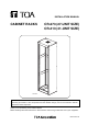
INSTALLATION MANUAL CABINET RACKS CR-273 (27-UNIT SIZE) CR-413 (41-UNIT SIZE) CR-413 Be sure to read this installation manual thoroughly before installing this Cabinet Rack. For the mounting procedures of the components and the relevant wirings, refer to the instruction manual attached to each component. Thank you for purchasing TOA's Cabinet Racks. Please carefully follow the instructions in this manual to ensure long, trouble-free use of your equipment.
TABLE OF CONTENTS 1. SAFETY PRECAUTIONS ................................................................................. 3 2. CONFIRMING INCLUDED PARTS 2.1. Complete Parts .................................................................................................. 4 2.2. Screws ............................................................................................................... 4 2.3. Accessories Other Than Screws ........................................................................
1. SAFETY PRECAUTIONS • Before installation or use, be sure to carefully read all the instructions in this section for correct and safe operation. • Be sure to follow all the precautionary instructions in this section, which contain important warnings and/or cautions regarding safety. • After reading, keep this manual handy for future reference.
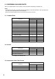
2. CONFIRMING INCLUDED PARTS Refer to the tables below to check quantity of each part before assembling the cabinet rack. Notes • Assemble the parts into a complete rack while checking the name label attached to each part and screw. For covers, the name labels are on their backsides. • Be sure to use the specified screws to mount the components in the rack. 2.1.
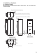
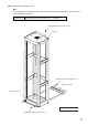
3. DIMENSIONAL DIAGRAMS 3.1. CR-273 (27-Unit size) Mountable depth from the panel mounting surface is 410 mm (16.14"). (402 mm or 15.83" to rear reinforcement bracket) 338 (13.31) 33 (1.3) ø6.5 (0.26) Knockout hole for fixing to a wall 4-ø17.5 (0.69) Eyebolt mounting hole (with a hole plug) 4-ø12 (0.47) Knockout hole for multiple rack support 470 (18.5) 566 (22.28) 435 (17.13) 20 (0.79) 40 (1.57) 10 (0.39) 175 (6.89) 89 (3.5) 1364 (53.7) 1013 (39.88) 69 (2.72) 33 (1.3) 200 (7.
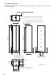
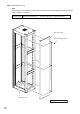
3.2. CR-413 (41-Unit size) Mountable depth from the panel mounting surface is 410 mm (16.14"). (402 mm or 15.83" to rear reinforcement bracket) 338 (13.31) 33 (1.3) ø6.5 (0.26) Knockout hole for fixing to a wall 4-ø17.5 (0.69) Eyebolt mounting hole (with a hole plug) 4-ø12 (0.47) Knockout hole for multiple rack support 470 (18.5) 435 (17.13) 566 (22.28) 20 (0.79) 115 (4.53) Cable entry opening 100 (3.94) Cable entry opening 360 (14.17) 440 (17.32) 6 200 (7.87) 220 (8.66) 280 (11.
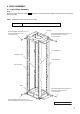
4. RACK ASSEMBLY 4.1. Cabinet Rack Assembly Note Be sure to check the name label ( before assembly. ) attached to each part and the location of each part to be positioned Step 1. Assemble the base, frames, and top plate. Screws used Bind head taptite screw type B 5 x 12 ..... 32 pieces Top plate Bind head taptite screw type B 5 x 12 (Use the same type of screw for the rear side.) Bind head taptite screw type B 5 x 12 (Use the same type of screw for the left side.
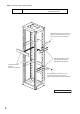
Step 2. Install the reinforcement brackets. Screws used Bind head taptite screw type B 5 x 12 ..... 12 pieces (CR-273) or 24 pieces (CR-413) Bind head taptite screw type B 5 x 12 (Use the same type of screw for the lower rear reinforcement bracket.) Side reinforcement brackets (One each at the left and right sides for the CR-273) Rear reinforcement brackets (One for the CR-273) Bind head taptite screw type B 5 x 12 (Use the same type of screw for the upper and left side reinforcement brackets.
Step 3. Install the top and base covers. Note As a protection film is attached to each cover to prevent it from being scratched and stained, remove it after installation completion. Screws used Bind head taptite screw type B 4 x 10 ..... 14 pieces Bind head taptite screw type B 4 x 10 Top cover Bind head taptite screw type B 4 x 10 Base cover (rear) Base cover (front) The figure shows the CR-413.
Step 4. Install the side covers. Note As a protection film is attached to each cover to prevent it from being scratched and stained, remove it after installation completion. Screws used Bind head screw M4 x 8 ..... 8 pieces (CR-273) or 12 pieces (CR-413) Side cover (right) Bind head screw M4 x 8 Side cover (left) The figure shows the CR-413.
Step 5. Install the rear covers. Note As a protection film is attached to each cover to prevent it from being scratched and stained, remove it after installation completion. Screws used Bind head screw M4 x 8 ..... 8 pieces (CR-273) or 12 pieces (CR-413) Bind head screw M4 x 8 Rear cover (2 rear covers for the CR-273) The figure shows the CR-413.
4.2. YA-706 Supporting Runner (option) Installation It is recommended that the optional Supporting Runner be installed to the rack so that the component can be easily drawn from the front of the rack for maintenance purpose or if the strength is particularly needed when installing the components in the rack. The figures below show the way to install the runner to the left side of the rack. Follow the same procedure for installation to the right side. Step 1.
4.3. BU-412 Blower Unit (option) Installation The installation instructions are printed on the BU-412. Step 1. Loosen 4 screws inside the top panel. (No need to remove them.) Top panel Step 2. Align the BU-412's front notches with the loosened front screws, and rear notches with the rear screws. Step 3. Tighten 4 loosened screws to secure the BU-412. 4.4. Screw Cover Installation Install the screw covers after installation completion of the components.
Step 2. Fit the supplied screw cover in the screw cover fittings. Screw cover fitting attached to the component Screw cover (accessory) CR-273: 6 pieces CR-413: 8 pieces 4.5. 2202 Microphone Hanger (option) Installation Install the optional 2202 Microphone Hanger to the rack's front frame to hang a handheld microphone. Make holes in the desired position on the front frame referring to the figure below.
4.6. Cable Duct (commercial item) Installation Separately prepare the cable duct to arrange wiring, then attach it with the following procedures. One each duct can be attached on both sides of the rear frames. The following materials are required when installing the cable duct. Max. 1,190 mm (3.9 ft) for CR-273 Max. 1,830 mm (6 ft) for CR-413 Oval hole (for 4 mm screw) Up to 30 mm (1.18”) Up to 60 mm (2.36”) [Cable duct] Mounting side 50 mm (1.97”) pitch Up to 30 mm (1.
Step 1. Attach the duct mounting bracket to the appropriate position on the rear frame. Step 2. Attach the cable duct to the duct mounting bracket. Screws used 4 x 10 tapping screw ..... 3 (per duct mounting bracket) Plain washer ................. 1 (per duct mounting bracket) Notes • The duct mounting bracket cannot be mounted at the place of the supporting runner. To mount, keep the duct mounting bracket a bit apart from the runner, and attach it to the frame.
5. CABINET RACK INSTALLATION 5.1. Installation Keep spaces around the rack as shown below to facilitate maintenance and operation. Wall surface Over 0.6 m (1.97 ft) Over 0.5 m (1.64 ft) CR-273 CR-413 Over 0.5 m (1.64 ft) Space required for maintenance and operation Over 2.0 m (6.56 ft) CAUTION Front Secure the rack to the floor with anchor bolts and to the wall with steel brackets to prevent it from being toppled over by earthquakes, etc. 5.2. Securing to Floor • 4-ø15 (0.
5.3. Securing to Wall A ø6.5 mm (0.26”) knockout hole is provided in the top cover of the rack. (See pages 5 and 6.) Remove the knockout with a screwdriver, and secure the top cover to a wall using the bracket (separately prepared). [Example] Bolt * Bracket * M6 bolt * Top cover for the CR-273 or CR-413 Anchor * Knockout hole (ø6.5 mm or 0.26”) Plain washer for M6 * Nut for M6 * * Commercial items 5.4. Securing Multiple Racks in Line Two ø12 mm (0.47”) knockout holes are provided in each side cover.
5.5. Installing Eyebolts for Rack Suspension Commercial suspension eyebolts can be installed on the top cover of the rack. Note that following commercial parts are required. M16 eyebolt ............................. 4 Nut for M16 .............................. 4 Plain washer for M16 ............... 4 Remove 4 hole plugs on the top cover, then install the eyebolts as illustrated below. Important The total weight of the rack system that can be suspended must not exceed 300 kg (661.38 lb).
URL: http://www.toa.