
Instruction Manual


9
9. SPECIFICATIONS
Standards Certified to the European Standard EN 54-24:2008
Loudspeaker for voice alarm systems
for fire detection and fire alarm systems
Certification No. 0359-CPD-0108
Certified to the International Standard ISO 7240-24: 2010 Sound-system
loudspeaker for fire detection and fire alarm systems
In Compliance with the British Standard BS 5839-8: 2008 14.8
Environment Type Type B (Outdoor applications)
Rated Noise Power 15 W (100 V line and 70 V line)
Rated Impedance 100 V line: 670 Ω (15 W), 1 kΩ (10 W), 2 kΩ (5 W)
70 V line: 330 Ω (15 W), 670 Ω (7.5 W), 1 kΩ (5 W), 2 kΩ (2.5 W)
Sensitivity 97 dB (1 W, 1 m at 330 Hz to 3.3 kHz pink noise)
94 dB (1 W, 1 m at 100 Hz to 10 kHz pink noise)
82 dB (1 W, 4 m at 100 Hz to 10 kHz pink noise)
Max.SPL 104 dB (15 W, 1 m at 100 Hz to 10 kHz pink noise)
92 dB (15 W, 4 m at 100 Hz to 10 kHz pink noise)
Frequency Response 150 Hz – 15 kHz
Coverage Angle (–6 dB) Horizontal: 140° (500 Hz), 90° (1 kHz), 90° (2 kHz), 100° (4 kHz)
Vertical: 200° (500 Hz), 155° (1 kHz), 90° (2 kHz), 60° (4 kHz)
Speaker Component 12 cm (5") cone-type (treated for splash proof)
Operating Temperature –20 ºC to +55 ºC (–4 ºF to +131 ºF)
Dust/Water Protection IP65
Cable Gland Size: PG 13.5
One cable gland is factory-installed.
For bridge connection, one cable gland can be added.*
Cable Connection Screw terminal (Steatite), can be bridge-connected
Applicable Cable Size Outer diameter: ø8.0 – ø12.5 mm
Conductor: Solid wire or 7-core wire
No bridge connection: 0.8 – 10 mm
2
(AWG18 – 7) for solid wire,
0.8 – 8 mm
2
(AWG18 – 8) for 7-core wire
Bridge connection: 0.8 – 2.5 mm
2
(AWG18 – 13) for solid wire,
0.8 – 1.5 mm
2
(AWG18 – 15) for 7-core wire
Finish Horn, Cover, and Terminal cover: ABS resin, off-white, paint
Bracket: Stainless steel
Net: Aluminum, gray, paint
Screw: Stainless steel
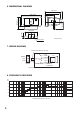
Dimensions 366 (w) x 230 (h) x 310 (d) mm (14.41" x 9.06" x 12.2")
Weight 3.0 kg (6.61 lb)
Accessory Terminal cover ..... 1
Notes
• The design and specifications are subject to change without notice for improvement.
• The specifications data was measured in an anechoic chamber, according to EN 54-24.
• Reference axis: Axis is on the center of horn-mouth and perpendicular to the horn-mouth.
• Reference plane: Plane is on the horn-mouth and perpendicular to the reference axis.
• Horizontal plane: Plane is containing the reference axis and perpendicular to the reference plane.
* Suppliable cable gland's part code and name: 525-52-011-70 Cable gland AVC PGB13.5-12 (GRY)
EN 54-24: 2008
11
0359-CPD-0108
0359