INSTRUCTION MANUAL CEILING SPEAKER SYSTEM F-2852CU2 Please follow the instructions in this manual to obtain the optimum results from this unit. We also recommend that you keep this manual handy for future reference.
TABLE OF CONTENTS 1. SAFETY PRECAUTIONS ............................................................................... 3 2. GENERAL DESCRIPTION ............................................................................. 4 3. FEATURES .......................................................................................................... 4 4. NOMENCLATURE AND DIMENSIONS ..................................................... 5 5. MOUNTING HARDWARE INSTALLATION .............................................
1. SAFETY PRECAUTIONS • Be sure to read the instructions in this section carefully before use. • Make sure to observe the instructions in this manual as the conventions of safety symbols and messages regarded as very important precautions are included. • We also recommend you keep this instruction manual handy for future reference.
2. GENERAL DESCRIPTION The F-2852CU2 is a flush-mounted Ceiling Speaker System that offers a wide frequency range of high-quality sound output. It is specifically designed to be mounted to a drop ceiling with use of the supplied tile bridge. 3. FEATURES • Two-way bass-reflex speaker system designed to provide a wide frequency range and high power handling capability. • Ideal for locations that have high ceilings or require true-to-life sounds.
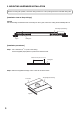
4. NOMENCLATURE AND DIMENSIONS Unit: mm (inches) ø245 (9 41/64) [Side] Approx. 600 (23 5/8) ø280 (11 1/32) [Front] 38 (1 1/2) Front grille (accessory) 236 (9 2/8) [Rear] Safety wire (accessory) Safety wire hook Mounting hole: ø250 (9 27/32) Tile bridge (accessory) Max. 202 (7 61/64) [Ceiling mounting] Choke bracket Max.
5. MOUNTING HARDWARE INSTALLATION Before mounting the speaker, check the ceiling structure is of drop ceiling with 2-foot standard ceiling tiles. [Installation view on Drop Ceilings] Caution Set the tile bridge so that both ends fit securely into the T-grids, even if the ceiling tile accidentally falls off. Tile bridge (accessory) T-grid Ceiling tile [Installation procedures] Step 1. Cut a ø250 mm (9 27/32") hole in the ceiling. Use the supplied paper pattern to position and trace the hole.
Step 3. Attach a safety wire to prevent the speaker from accidentally falling. To attach, tie one end of the supplied safety wire around the speaker's safety wire hook, and tie its snap ring around a secure C-channel bar or suspension pipe.
6. WIRING 6.1. Wiring through Hard or Flexible Conduit Note The choke bracket equipped with the speaker has not been evaluated by UL, for conduit connection and UL514B Standard. Flexible conduit of 3/8 or 1/2 inch trade size and the UL514B conduit fitting of the same trade size can also be used. When using the UL514 listed conduit fitting, detach the equipped choke bracket and mount the conduit fitting instead. Loosen the screw to allow the speaker cable to pass through.
6.2. Wiring with Naked Cables Loosen the screw to allow the speaker cable to pass through. Plug the wired input connector into the speaker's socket, then pull the speaker cable from the choke bracket. (For wiring the input connector, refer to p. 10.) Choke bracket Retighten the screw to fix the speaker cable. Note Ensure that the speaker cable is securely fixed.
7. CABLE CONNECTION TO INPUT CONNECTOR Recommended cable types • Solid copper wire: ø1.0 – ø1.6 mm (equivalent to AWG 18 – 14) • Stranded copper wire: 0.75 – 2.5 mm2 (equivalent to AWG 18 – 14) Cover mounting screw Step 1. Loosen the 2 cover mounting screws, and rotate the connector cover in the direction indicated by the arrow in the figure at right. Speaker unit Connector cover Removable input connector Step 2.
8. SPEAKER INSTALLATION Caution Before mounting, check to be sure that the speaker's 4 mounting tabs are turned inside the unit as shown in the figure. If turned outward, the speaker cannot be inserted through the mounting hole. In Out Mounting tab Step 1. Insert the speaker through the mounting hole till it contacts the ceiling panel. While doing so, avoid directly touching the speaker's diffuser section.
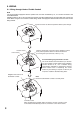
Step 3. Set the input power. Turn the input selector switch (on the unit's front) to set it to the desired input impedance. (Factory-preset to 170 Ω.) Step 4. Attach the front grille. Align the tabs (4 places) on the back side of the grille with the corresponding notches in the unit, then rotate the grille to full stop in the direction indicated by the "LOCK" arrow.
9. REMOVING THE SPEAKER FOR MAINTENANCE 9.1. Detaching the Front Grille 1 Turn the front grille counterclockwise to full stop, then lightly pull it downward. Tip The front grille employs a double-locking system. If the grille cannot be detached when lightly pulled downward, it likely has not yet been fully rotated back to the detachment position. In such cases, take care to rotate the grill fully counterclockwise in order to release the lock. Unlock Front grille 2 Pull lightly. 9.2.
10. REPAINTING THE SPEAKER FRONT GRILLE Note: Be sure to detach the front grille from the speaker before repainting. Step 1. Clean the front grille before painting. Wipe with a soft cloth dampened in a detergent. Caution Do not use thinner or other volatile liquids to clean the grille. Step 2. Spray on a uniform, thin coat of paint. Cautions • Avoid painting with a roller or brush, as the grille mesh holes could become clogged with paint.
12. SAFETY AGENCY COMPLIANCE This product is for indoor use only. • General signaling speaker, UL1480 Category UEAY and CAN/CSA C22.2 No. 205 Category UEAY7 Products Listed under these categories are suitable for use in general (non-fire alarm) signaling service in conjunction with compatible Listed audio equipment, the combination of which is intended to be installed in accordance with the applicable requirements of the National Electrical Code (NEC) and the local authority having jurisdiction.
13. SPECIFICATIONS Enclosure Rated Input Power Handling Capacity Impedance Frequency Response Sound Pressure Level Speaker Component UL Cord Mounting Hole Input Terminal Usable Cable Finish Dimensions Weight Bass reflex type 60 W (High Impedance) Continuous pink noise: 90 W (8 Ω), 60 W (16 Ω), 70 V line: 83 Ω (60 W), 170 Ω (30 W), 330 Ω (15 W), 670 Ω (7.5 W), 3.3 kΩ (1.5 W) 25 V line: 83 Ω (7.5 W), 170 Ω (3.7 W), 330 Ω (1.9 W), 670 Ω (0.9 W), 3.3 kΩ (0.