INSTALLATION MANUAL BASIC INSTALLATION RACK-MOUNTED EMERGENCY PA SYSTEM FS-970 SERIES MODEL NUMBERS : FS-971 FS-972 FS-973 Installation Precautions (For Sales Shops and Installers) • When inspecting the speaker line insulation, disconnect the speaker lines from the PA system.
TABLE OF CONTENTS 1. SAFETY PRECAUTIONS ............................................................................................................. 4 2. SUPPLIED MANUALS .................................................................................................................. 6 3. BEFORE STARTING INSTALLATION 3.1. System Summary ........................................................................................................................... 7 3.2. About the Emergency Power Supply 8 3.
9. RACK INTER-PANEL CONNECTION 21 9.2. Pre-amplifier Panel PP-025B Connection ....................................................................................... 22 9.3. Power Amplifier Panel Connection ................................................................................................. 23 9.1. FS-971 System Panel Connection Diagram ................................................................................... 9.4. Emergency Power Supply Panel DS-029B Connection 24 24 9.4.3.
1. SAFETY PRECAUTIONS • Be sure to read the instructions in this section carefully before use. • Make sure to observe the instructions in this manual as the conventions of safety symbols and messages regarded as very important precautions are included. • We also recommend you keep this instruction manual handy for future reference.
CAUTION When Installing the Unit When the Unit is in Use • Never plug in nor remove the power supply plug with wet hands, as doing so may cause electric shock. • Make sure to observe the following handling precautions so that a fire or personal injury does not result from leakage or explosion of the battery. · Do not short, disassemble, heat nor put the battery into a fire. · Do not solder a battery directly. · Be sure to use the specified type of batteries.
2. SUPPLIED MANUALS The following manuals are supplied with the emergency PA system. 1 Emergency PA System FS-970 Series Installation Manual 2 Emergency PA System FS-970 Series Installation Manual - Basic Installation 3 Emergency PA System FS-970 Series Installation Manual - Applied Installation 4 Emergency PA System FS-970 Series Installation Manual - Writing The book you are reading now • Read only the manuals that are suited for your purpose.
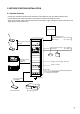
3. BEFORE STARTING INSTALLATION 3.1. System Summary • The FS-971 and FS-973 permit system expansion of up to 330 lines and up to 330 emergency zones. • The FS-972 permits system expansion of up to 50 lines and up to 50 emergency zones. • Each of the FS-971, FS-972 and FS-973 permits connection of eight emergency remote control units and eight general remote control units. Fire alarm system No.
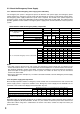
3.2. About the Emergency Power Supply 3.2.1. Selection of the emergency power supply panel and battery The emergency PA system is designed to operate on both the main power supply and emergency power supply. Because the emergency system needs to be operated for ten minutes or more during a power failure, the emergency power supply suited to the system scale is required. The FS-970 series systems require the emergency power supply panel DS-029B and Ni-Cd battery NDC-2435 or NDC-2460.
480W 720W 1440W 1080W 1800W 2 7AH 7AH 4 2 1 b 6AH 7AH 2 1 2 c 140 110 90 70 60 50 40 40 30 330 270 220 190 160 140 130 110 100 330 310 260 220 190 170 150 140 120 12AH 2 c 2 4 3 5 12AH 6AH 7AH 12AH 6AH 7AH 12AH 6AH 7AH 12AH 6AH 7AH 12AH 7AH 12AH 12AH 12AH 18AH 18AH 18AH 24AH 24AH 24AH 30AH 30AH 30AH 2 2 2 2 2 3 6 5 7 2 2 4 6 6 4 3 5 4 2 3 4 4 2 2 2 3 3 3 3 3 2 c d c c c c c c c c c c d No.
5. INSTALLATION PROCEDURES 1. Equipment rack assembly and installation Page 11 2. Before installing rack components in the rack Page 15 3. Rack component mounting Page 18 4. Rack inter-component connections Page 21 5. Operation/expansion panel address setting and connection to external lines Page 38 6. Connection inspection Page 45 7.
6. EQUIPMENT RACK ASSEMBLY AND INSTALLATION 6.1. Poor Installation Locations Avoid installing the rack in the following locations. • Locations that may be exposed to fire, heat or direct sunlight (ambient temperature should be between 0°C and 40°C). • Locations that may be exposed to rainwater, steam or high humidity. • Locations exposed to vibration. • Locations offering limited space at the rear of the rack for inspection. • Locations where particles of metal or dust accumulate, or near chemicals or oil.
6.3. Rack Installation The emergency rack system must be installed as shown in the figure below. Wall surface, etc. Over 0.6 m Over 0.5 m CR-272 CR-412 CR-412-6 Front Over 0.5 m Space for inspection and operation Over 2 m • To prevent the equipment rack from falling down due to an earthquake, etc., secure the rack to the floor with anchor bolts and to the wall with brackets. • When installing the general rack system, also allow for the above spacing to facilitate maintenance. 6.4.
6.5. Securing the Rack CR-412-6 to the Floor Four anchor bolt mounting holes (ø15 mm) are provided in the rack bottom surface to secure the rack to the floor. Referring to the figure below, make holes in the floor, then secure the rack to the floor using four M10M12 anchor bolts. Front 615 100 400 460 (115) Cable entry opening 360 Anchor bolt mounting hole (ø15 mm, 4 places) 440 566 6.6. Securing the Rack to the Wall (for Prevention of the Fall) A knock-out hole (ø6.
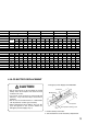
6.7. Rack Suspension using Eyebolts Eyebolts for suspension can be mounted to the rack top panel. • Purchase the following parts separately in the market. Eyebolts M16 ............... 4 pieces Nut M16 ....................... 4 pieces Plain washer M16 ........ 4 pieces Remove four rubber hole covers provided on the top panel, and install eyebolts (4 places) in the exposed holes as shown in the figure. Important: The maximum rack system weight for 4-point suspension is 300 kg. Remove this rubber hole cover.
7. BEFORE MOUNTING THE COMPONENTS IN THE RACK 7.1. Integrated Control Panel EP-0510 • Chime Switch Installation To activate the external chime device or the CK-025 Chime Unit built in the PP-025B Pre-amplifier, install the chime switch (supplied with the EP-0510) as shown below. You may skip the following installation procedures if the chime does not need to be activated from the EP-0510. 1. Push to break the chime switch hole on the Operation Panel. 2.
7.2. Pre-amplifier Panel PP-025B • Chime Unit (CK-025) Installation Note: Install the Chime Unit in the Pre-amplifier Panel before mounting the Pre-amplifier Panel in the rack. 1. Remove the front panel, top panel and rubber hole cover on the front panel. Top panel Screw (M3x6) Hole cover Front panel Screw (M3x6) 2. Select the chime tone type for the Chime Unit to install by changing the jumper connector position on JP1 through JP3 on the Chime Unit's circuit board.
4. Connect one end of the connector cable supplied with the Chime Unit to the Chime Unit' s connector, and the other end to connector CN17 on the PP-025B's internal circuit board. Chime Unit is used. (USE position) Chime Unit is not used. (NO USE position) Front JP1 CHIME SET USE NO USE JP1 CHIME SET USE NO USE Jumper connector Jumper connector Chime Unit CK-025 JP1 CHIME SET CN17 CHIME Connector cable supplied with the CK-025 5.
8. COMPONENT INSTALLATION This section describes the points of installation you need to bear in mind when mounting the following main components in the rack. 8.1. Integrated Control Panel It is highly recommended that all the switches on the emergency operation panel be positioned at the height of 0.8 to 1.5 m from the floor. Therefore, the Integrated Control Panel EP-0510 and the Expansion Operation Panels EP-029-10 and EP-029-20 must be positioned at the height shown below.
8.3. Emergency Power Supply Panel You need to mount the perforated panel (PF-013B, etc.) above and below each Emergency Power Supply Panel DS-029B. However, up to two Emergency Power Supply Panels may be stacked without the perforated panel between them. Equipment rack Equipment rack Perforated Panel Emergency Power Supply Panel Perforated Panel Emergency Power Supply Panel 8.4.
8.5. Power Amplifier Panel Mounting Position • You need to mount the perforated panel (PF-013B, etc.) above and below each power amplifier panel. However, up to two power amplifier panels may be stacked without the perforated panel between them provided each amplifier output power is less than 120 W. • Mounting examples 1. Power amplifier panel rated at 120 W or less (PA-1230B) Equipment rack Perforated panel Power amplifier panel 2.
9. RACK INTER-PANEL CONNECTION 9.1. FS-971 System Panel Connection Diagram FS-971-36NA Supplied with EP-029. Supplied with DS-029B. Supplied with EP-0510. Supplied with JP-0410. Supplied with EP-029. Supplied with JP-0410. Supplied with PP-025B. Supplied with DS-029B.
9.2. Pre-amplifier Panel PP-025B Connection • You can install the Chime Unit in the Pre-amplifier Panel. (Refer to p. 16.) • Input 1-A jack is located on both the front and rear panels. When both jacks are simultaneously used, the broadcast from the front panel is allowed to go through. • Input 1 takes precedence over Inputs 2 and 3, while Input 2 takes precedence over Input 3. Connect a BGM player to Input 3, and the microphone and chime to Input 1 or 2 depending on the degree of their importance.
9.3. Power Amplifier Panel Connection • Use the same output line voltage when connecting power amplifier panels for parallel operation. You can connect up to three power amplifier panels of the same kind in parallel. Important: Make connection so that the total of speaker rated input power is less than 1 kW for a group of five consecutive speaker lines (i.e. lines 1-5, 6-10, etc.). • Do not use the 4 Ωoutput terminal for the rack PA system. • Refer to p.
9.4. Emergency Power Supply Panel DS-029B Connection 9.4.1. Battery connection Internal Ni-Cd batteries are optional. Depending upon the output and number of power amplifier panels to use, and the number of connected emergency remote control units, select the proper type of battery. After installing the selected battery in the DS-029B, make connections. For battery selection, refer to p. 8 "About the Emergency Power Supply".
9.4.3. About the operation of the Emergency Power Supply Panel DS-029B When the AC power is supplied and the Emergency Activation terminal is not shorted (standby status).... Current flows in coils D and E, and contact points d and e are as shown below. 24 VDC is not sent to REMOTE (left) or outputs 1-4.
When the emergency function is operated while the AC power is cut off (power failure).... Current flows in Coil F in the Junction Panel JP-0410 and contact point f switches, thereby causing the 24 VDC power output from REMOTE (left) of the Emergency Power Supply Panel DS-029B to return to the DS029B's REMOTE (right). As a result, the current flows in Coils B and C and contact points b and c switch as shown below, transmitting 24 VDC to outputs 1-4.
9.4.4. Connections Connections of the Emergency Power Supply Panel DS-029B are classified into four methods a, b, c, and d depending on the composition selected in the section "About the Emergency Supply Panel" on p. 8. Because the operation and control sections are fundamental to the emergency broadcast system, any failure in their operation will disable the function of the entire system.
Connection method b for the DS-029B In this method, two batteries (one DS-029B unit) are connected to supply power to the operation/control sections and power amplifier panel separately.
Connection method c for the DS-029B In this method, three or more batteries (multiple DS-029B connection) are connected to supply power to the operation/control section and power amplifier panel separately.
Connection method d for the DS-029B In this method, three or more batteries (multiple DS-029B connection) are connected. A single DS-029B unit contains two batteries: one to supply power to the operation/control section and one to supply power to the power amplifier panel.
9.4.5. Connecting a single emergency power supply panel to power amplifiers The figure below shows the method of connecting the Emergency Power Supply Panel DS-029B to the power amplifier panel. Refer to the figure when expanding power amplifier panels or designing the power amplifier rack. • Only a single power amplifier panel (up to 120 W) can be connected per output terminal of the emergency power supply panel.
9.5. Junction Panel JP-0410 Connection 9.5.1. Connecting the Junction Panel's rear-mounted terminal block 1. 24V IN/OUT terminals • The power capacity of the JP-0410's built-in power supply is 2 A. Use the 24V IN/OUT terminals when the power capacity is insufficient because of an increase in the number of zones or remote controls. (Refer to p. 35.) • The junction panel is shorted between IN and OUT terminals using a jumper wire at the factory.
9.5.2. Connecting the AC power supply of the Junction Panel JP-0410 • The Junction Panel JP-0410 supplies the AC power to each component mounted in the rack. • AC power is always supplied to the UNSWITCHED AC outlets. Be sure to connect the Emergency Power Supply Panel to the UNSWITCHED outlet to keep its internal batteries fully charged. Make sure that the DC Power Supply Panels AD-011 and AD-031B are also connected to the UNSWITCHED outlet.
9.6. DC Power Supply Panel Connection 9.6.1. When the DC power supply panel is not required (i.e. when you can do with the junction panel's internal power supply).... The power capacity of the Junction Panel's (JP-0410) internal power supply is 2 A in maximum output current. Note the total current of connected components and external equipment. If their total current exceeds 2 A, the power supply must be expanded.
9.6.2. When expanding the power supply for external equipment Let us assume that one expansion power supply is added to the system solely to cover the shortage of power to be supplied to external equipment as the result of connecting many external equipment or mounting many components in the rack. Note: Remove the jumper wire placed between the 24V IN and OUT terminals of the terminal block located on the rear panel of the Junction Panel JP-0410.
9.6.4. Connection between DC power supply panel and Expansion Operation Panel EP-029 Make connections using the optional expansion power cable YR-931. Note the polarity when connecting. The red cord is for 24 VDC (+), while the black cord is for 24 VDC (–). YR-931 EP-EP cord Integrated Control Panel EP-0510 Use this cord to disconnect the power supply. Supplied with EP-029.
9.6.5. Connection between DC power supply panel and Expansion Junction Panel JP-039 Use the optional expansion power cable YR-931 for connection. Note the polarity when connecting. The red cord is for 24 VDC (+), while the black cord is for 24 VDC (–). YR-931 JP-JP cord Junction Panel JP-0410 Use this cord to disconnect power.
10. SETTING OF THE INTEGRATED CONTROL PANEL EP-0510 Use switches SW1-SW4 on the EP-0510's control circuit board for setting. ON 12345678 SW1 ON ON ON 12345678 12345678 12345678 SW2 SW3 SW4 Set the following items using the switches SW1-SW4. • [Warning Announcement Interlock] or [Warning Announcement Non-Interlock] mode (SW4-1) Use SW4-1 switch to set either mode.
• Evacuation Announcement interval (SW4-4 through SW4-8) Time intervals can be set for 30 seconds to 15 minutes 30 seconds in 30 seconds units. ON SW4 4 5 6 7 8 ON 8 minutes 4 minutes 2 minutes 1 minute 30 seconds OFF 0 0 0 0 0 1 2 3 4 5 6 7 8 SW4 Evacuation Announcement interval • All-zone announcement interval (SW2-3 through SW2-8) Time intervals can be set for "OFF", "0 second" or "30 seconds to 15 minutes 30 seconds" in 30 seconds units.
• Main Rack BGM broadcast (SW1-1 and SW1-2) Set equipment that can initiate Main Rack BGM. Both switches are set to OFF at the factory so as to allow the Main Rack BGM to be played from the [Main rack system and all emergency remote control units].
11. EXPANSION PANEL ADDRESS SETTING 11.1. Expansion Operation Panel EP-029 When your system contains the 10-Zone Expansion Operation Panel EP-029-10 or 20-Zone Expansion Operation Panel EP-029-20, the address number needs to be assigned to each expansion unit. • Use consecutive numbers starting with 0 to set the address.
12. CONNECTING THE RACK-MOUNTED COMPONENTS TO EXTERNAL LINES 12.1. Names of the Front-Mounted Terminal of the Junction Panel JP-0410 12.2. AC Power Supply Connections The power supply circuit of an emergency broadcast system must be a dedicated circuit, and the circuit breaker after a branch point must be marked with the indication of the dedicated power supply.
12.3. Speaker Connections Connect speaker cables to terminals R,N, and C, as shown below. (The R wire may be omitted when no attenuator is used.) When Expansion Junction Panel JP-039 is additionally used, make connections in like manner. Notes • The maximum connectable speaker wattage per line is 200 W. When exceeding 200 W, divide the line into two or more groups. • Connect speaker cables so that the total of rated inputs of every five speaker lines (1-5, 6-10, etc.) is less than 1 kW.
12.4. Connections to the Automatic Fire Alarm Systems By connecting the emergency PA system to an automatic fire alarm system, voice alarms can be automatically provided as soon as the PA system receives a fire signal from a fire detector. It must be seen to that the floor signal lines (EL) are connected to the junction panel terminals of their corresponding floors. Because fire confirmation signals (EF) are also important to automatic broadcast, connect their cables properly.
13. CONNECTION INSPECTION 13.1. Inspection of Connections and Wiring • After all connections are completed, inspect the connections and wiring again before turning on the AC breaker of Junction Panel JP-0410. • Ensure that cables are correctly connected between components. Also, check external wiring for connection errors and wiring omissions. 13.2. Adjustment and Measurement of Power Circuitry 13.2.1.
13.3. Speaker Line Adjustment and Measurement 13.3.1. Speaker line impedance measurement (using impedance meter) Measure the impedance of each speaker line, then measure the total impedance of all lines. Record the planned impedance and measured impedance for future maintenance and inspection. If the planned impedance is notably different from the total impedance, inspect individual lines again to find and remove the cause. Impedance of arbitrary wattage can be calculated using the formula below.
13.3.2. Speaker line insulation resistance measurement (Measuring instrument: Megger) Measure between the ground and the cable for each line. Do not measure between cables, as this can damage both the speaker and matching transformer. It is recommended that wiring be performed so that the following resistance values are obtained.
13.4. Speaker Sound Pressure Level Measurement [Measuring instrument: Sound level meter (A weighting network characteristics)] Measure the output sound pressure level at a 1 meter distance from the center of the installed speaker when the voice alarm second signal is sounding at the rated output. Check to confirm that the output sound pressure level is greater than the value shown below depending on the type of speaker.
15. SPECIFICATIONS OF THE MAIN RACK COMPONENTS • Integrated Control Panel EP-0510 Power Source Current Consumption Emergency Alarm Fire Floor Information Fire Floor Information Language Fire Alarm Interlock Mode Two-floor Interlock Mode Warning Announcement Interlock Evacuation Announcement Interval All-zone Broadcast Interval Input Output Output Control Broadcast Status Output Function Monitor Speaker Finish Dimensions Weight Accessories 24 VDC 0.
• 20-Zone Expansion Operation Panel EP-029-20 ([ ] = 10-Zone Expansion Operation Panel EP-029-10.) Power Source Current Consumption Output Control Finish Dimensions Weight Accessories 24 VDC 180 mA [100 mA] 20 zones [10 zones] Black 482 (w) x 88.4 (h) x 71.8 (d) mm 1.6 kg [1.
Power Connection Section Input Output Control External Control Output External Control Input AC Power Output Finish Dimensions Weight Accessories 24 V IN, M4 screw terminal 24 V OUT, M4 screw terminal Emergency DS activation output: 24 VDC, 0.1 A, M4 screw terminal Emergency DS control input: 24 VDC, 5 A, M4 screw terminal Battery check output (up to 50 DS-029Bs connectable): Open collector output, rated voltage: 30 VDC, current capacity: 0.
• Junction Panel JP-0410 (L version) Power Source Power Consumption Speaker Line Line Short Protection Automatic Fire Alarm System Input Emergency Remote Control Unit Input Output Control General Remote Control Unit Output Control Power Connection Section Input Output Control 52 110 VAC, 50/60 Hz 95 W (120 VA) 10 lines each of R (Attenuator-free), N (Normal), and C (Common), M3.
External Control Output External Control Input AC Power Output Finish Dimensions Weight Accessories Emergency cut-off 24 V: 24 VDC, 0.5 A, M3.5 screw terminal 24 V in emergency: 24 VDC, 0.1 A, M4 screw terminal EB 1 and 2: Relay output, contact rating: 30 VDC, 1 A, M3.5 screw terminal Emergency contact: Relay output, contact rating: 30 VDC, 1 A, M3.5 screw terminal Remote control: Relay output, contact rating: 30 VDC, 1 A, M3.
• Pre-amplifier Panel PP-025B PP-025B Power Source Current Consumption Input Output Frequency Response Tone Controls S/N Ratio Distortion Priority3 Finish Dimensions Weight Accessories 24 VDC Less than 200 mA Input 1-A: –2 dBV/–62 dBV (changeable), 600 Ω, balanced, phone jack Input 1-B: –2 dBV, 600 Ω, balanced, phone jack Input 2-A: –2 dBV/–62 dBV (changeable), 600 Ω, balanced, phone jack Input 2-B: –2 dBV, 600 Ω, balanced, phone jack Input 3-A: –2 dBV, 20 kΩ, unbalanced, phone jack Input 3-B: –2 dBV, 20
• Emergency Power Supply Panel DS-029B Power Source Power Consumption Applicable Battery Charging Method Charging Current Battery Check Circuit Finish Dimensions Weight Battery Weight Accessories 110/120/220/240 VAC (changeable), 50/60 Hz 24 W (30 VA) Sealed Ni-Cd battery, up to 2 batteries are usable. NDC-2435 (3500 mAH/5 HR), optional NDC-2460 (6000 mAH/5 HR), optional Trickle charging NDC-2435: 88 mA NDC-2460: 150 mA Automatic judgment by check start signal Black 482 (w) x 88.4 (h) x 346.1 (d) mm 5.
Printed in Japan 133-12-580-3D