TRANTEC S-D7802 Digital wireless receiver OPERATING INSTRUCTIONS Thank you for purchasing Trantec Digital Wireless Receiver. Please carefully follow the instructions in this manual to ensure long, trouble-free use of your equipment.
TABLE OF CONTENTS 1. SAFETY PRECAUTIONS .............................................................................. 4 2. GENERAL DESCRIPTION ........................................................................... 5 3. FEATURES ............................................................................................................. 5 4. HANDLING PRECAUTIONS ....................................................................... 5 5. Installation and Connection Procedures ............... 6 6.
13. Tips on use ................................................................................................... 29 13.1. Transmission Information Check of the Digital Wireless Microphone ................ 29 13.2. Global Save and Global Load of Receiver Settings ........................................... 30 13.3. User Name Settings ........................................................................................... 31 14. Rack mounting ...........................................................
1. SAFETY PRECAUTIONS • Before installation or use, be sure to carefully read all the instructions in this section for correct and safe operation. • Be sure to follow all the precautionary instructions in this section, which contain important warnings and/or cautions regarding safety. • After reading, keep this manual handy for future reference.
When the Unit is in Use • Do not place heavy objects on the unit as this may cause it to fall or break which may result in personal injury and/or property damage. In addition, the object itself may fall off and cause injury and/or damage. • Switch off the power, and unplug the power supply plug from the AC outlet for safety purposes when cleaning or leaving the unit unused for 10 days or more. Doing otherwise may cause a fire or electric shock.
5. Installation and Connection Procedures Installation and Connection Antenna Installation See p. 14. Rack Mounting See p. 32. Equipment Connection See p. 16. Activating the Receiver Receiver Settings See p. 11. Microphone/Transmitter Settings See the microphone's or transmitter's instruction manual. Settings and Testing Transmission and reception test using a wireless microphone Interferes with other microphone being used.
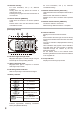
6. Nomenclature AND FUNCTIONS [Front Panel] 3 2 4 Unit Display Section 5 Function Display Section 1. Power switch Press this switch to turn the power on, and press it again to turn off the power. 2. Power indicator Lit when the power is on. 3. Antenna mounting kit mounting holes For more information, see p. 19, "Mounting the Antenna on the Receiver's Front Panel." [Front Monitoring Section] 6 7 UNIT 1 UNIT 2 MIN PHONES VOL MAX 3 4.
12. Network reset key For more information, see p. 27, “Network Function.” Holding down this key places the receiver in maintenance mode. Pressing this key again sets the receiver back to normal mode. 13. Remote indicator [REMOTE] Lights when the receiver is in remote operation mode. Flashes when a PC uses the Receiver location confirmation function. For more information, see p. 27, “Remote/ Local Mode Setting.” 14.
[Rear Panel] 22 100 – 240V 23 24 25 26 27 28 29 500mA 50/60Hz 30 31 32 33 34 35 22. Functional earth terminal To ensure stable operation, be sure to ground this terminal. Note This terminal is not for protective earth. 23. Word clock input terminal [WORD CLOCK IN] Allows connection to a word clock signal source. 24. AES/EBU output connector XLR-3-32 or equivalent connector (Pin No. 1: Ground, Pin Nos. 2 and 3: Signal), AES/EBU Digital output connector.
35. Mixing output jack Phone jack, –10 dB*, unbalanced (at reference output). Connect to the Line (Auxiliary) input terminal of the connected device. Outputs audio signals from Unit 1, Unit 2, and mixing input after they are all mixed. Interlocks with the front-mounted Headphone output unit selector key. 36. Unit 2 audio output jack (unbalanced) Phone jack. Unbalanced independent audio output of the Unit 2. Connect to the microphone input terminal or line input terminal of the connected device. 37.
7. Settings and Confirmation Procedures 7.1 Receiver Setting Operation Two operation modes are available for receiver settings: • Local mode: Change and confirm settings using the receiver's LCD screen and keys. • Remote mode: Change and confirm settings using dedicated software installed on a PC connected to the receiver via a network. Explained herein is a Local mode. For the Remote mode, refer to the S-D7000 Series Monitoring Software instruction manual contained in the supplied CD. 7.2.
7.3. Settings and Confirmation Procedures for Each Setting Item 7.3.1. Operation menu display's LCD screen after power-on U 1 : 6 0 6 . 2 5 0 M H z U 2 : 6 0 6 . 2 5 0 M H z Confirm that the front panel Remote indicator remains unlit. If the indicator is lit, follow the procedure below to switch the operation mode to "Local." 7.3.2.
7.4. Receiving frequency settings 7.4.1. Setting procedures Step 1. Display "2 FREQUENCY" in the Operation menu display. Step 2. Press the Right key to go to "FREQUENCY MENU." Step 3. Select the unit using the Up and Down keys. Step 4. Press the Right key, then select the Group number using the Up and Down keys. Step 5. Press the SET key. The selected group is confirmed and an asterisk ( ) is displayed before the group number. Step 6. Select the channel number.
8. Antenna Installation 8.1. Examples of Antenna Installation Appropriate to Room Sizes Example using 2 antennas (Facing each other) Example using 4 antennas to cover around the stage Approx. 50 m Approx. 30 − 50 m Antenna Example using 2 antennas (on the same wall surface) Example using 6 antennas in total (on the surrounding wall surfaces) Approx. 30 − 50 m Approx. 50 − 80 m Approx. 50 – 80 m 5 − 20 m Approx. 30 – 35 m Approx. 30 – 35 m Approx.
8.2. Points of Installation Point 1 Install both antennas where a talker having the wireless microphone can directly see them within 20 – 30 m (or at least within 40 - 50 m when placing outdoors). (This is to ensure that the other antenna can receive signals in a good condition if dropouts occur in the receiving range of either one of the 2 antennas. This is the only thing to keep in mind when installing antennas no matter what room shapes are.
9. Connection Examples 9.1. Using a Single Receiver Use the supplied antenna, or optional YW-7520 or YW-7570. Be sure to connect 1 antenna to each of both A and B antenna connectors.
9.2. Sharing an Antenna between 2 Receivers After connecting an antenna to one receiver, connect that receiver's antenna output (CASCADE OUT) to another receiver's antenna input (ANTENNA IN) with a BNC cable. When an antenna is shared, the RF Cascade indicator lights on the receiver where the antenna is mounted. This application example serves to configure the system where up to 4 microphones are used in a relatively small area. Notes • Use the supplied antenna, or optional YW-7520 or YW-7570.
9.3. Sharing an Antenna among 3 or more Receivers Use an S5-ADU Antenna Distributor. Connect the distributor's antenna output to the receiver's antenna input (ANTENNA IN). Connect the antenna to the distributor's antenna input (ANTENNA IN). Note Use the supplied antenna, or optional YW-7520 or YW-7570. Be sure to connect one each of antennas to both A and B antenna input connectors.
9.4. Mounting the Antenna on the Receiver's Front Panel It is possible to install the supplied antennas on the receiver's front panel using the supplied front mount cord with BNC plug (65 cm). Detach the plug cap on the rack mounting bracket, run the cable's BNC jack through the mounting hole, then secure the BNC jack with the supplied washer and nut. Connect the cable's BNC plug to the receiver's rear-mounted Antenna input connector.
9.5. Monitoring with Headphones Press the key for Unit 1 or Unit 2 to select the tuner unit to monitor. Pressing both keys allows mixed audio from both units to be heard. 9.5.1. Headphones Cascade Connections Audio output from multiple receivers can be monitored from a single headphones jack at the last-connected receiver by connecting receiver mixing inputs and outputs in cascade. Audio from the tuner units selected with the unit selector keys are mixed together and output to the headphones jack.
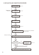
10. HOW TO CHECK AND DEAL WITH INTERFERENCE 10.1. Order of Actions (Action Flowchart) Check out the radio wave condition of the problematic channel using the ID ON/OFF function. Any interference? No See p. 22, "Received Signal Check by way of ID ON/OFF Setting." Use as is. Yes Change the group/channel numbers to those of idle channels. See p. 13, "Receiving frequency settings." It is convenient to use "CHANNEL SCAN" when selecting idle group/channel numbers. See p.
10.2. Received Signal Check by way of ID ON/OFF Setting 10.2.1. What is ID ON/OFF setting? ID ON/OFF setting function is provided to check the radio wave condition of the receiving frequency when interference occurs during use or when the new group and channel number is assigned to the receiver. 10.2.2. Setting procedures Step 1. Display "6 UTILITY" in the Operation menu display. Step 2. Press the Right key to go to the UTILITY MENU. Step 3. Select "2 CHANNEL IDENTITY" using the Up and Down keys. Step 4.
10.3. Idle Channel Search by way of Channel Scan 10.3.1. What is channel scan? Cannel scan is a function to search and display the idle channels. Setting the channel number based on the result from channel scan will decrease the possibility of interference received. 10.3.2. Setting procedures Step 1. Display "6 UTILITY" in the Operation menu display Step 2. Press the Right key to go to UTILITY MENU. Step 3. Select "1 CHANNEL SCAN" using the Up and Down keys. Step 4.
10.4. Reducing Radio Interference by way of Antenna Attenuator Up to 2 antennas can be connected to the receiver. The receiver is equipped with a built-in antenna attenuator for each antenna. Attenuation level can be easily set by the operation menu on the front panel. The following table shows the rough relationship between each antenna attenuator level and transmission distance. Normally set it at "0 dB" level.
11. Digital Audio Output 11.1. Word clock settings for the digital audio signal output Digital audio signals of 48 kHz sampling 24 bit format by the internal clock can be output. In addition, signals can also be output synchronizing with external word clock by inputting a word clock from external clock generator. Frequency range of the enterable word clock is 32 to 96 kHz. Word clock input impedance is 75Ω.
11.2. Termination Impedance Setting of the Word Clock Input Input impedance for the coaxial cable input of the external word clock can be selected. Use rear-mounted terminal selector switch to select "Open" or "75 Ω." TERM OCK OPEN 75Ω Notes • When using the word clock distributor Connect the word clock signal to be output from the word clock generator to the receiver's word clock input terminal in a one-to-one relationship via the dedicated distributor.
12. Network Function 12.1. Function Overview The S-D7802 TRANTEC Digital wireless receiver can perform mainly status monitoring and controls of the receiving system in real time with the dedicated system monitoring software installed into a PC by connecting the receiver's LAN connector and the PC with an Ethernet cable.
12.3. Output Unit Settings of the Packet Audio Signal Packet audio signals can be transmitted not only to the PC but also to the TOA Network Audio Adapters NX100 and NX-100S via an Ethernet cable. In this case, it is possible to set which tuner unit's audio signals to be output to the network. 12.3.1. Setting procedures Step 1. Display "9 NETWORK" in the Operation menu display Step 2. Press the Right key to go to NETWORK MENU. Step 3. Press the Up and Down keys to go to MONITOR UNIT. Step 4.
12.6. Receiver Name check Checks the receiver's name. 12.6.1. Setting procedures Step 1. Display "9 NETWORK" in the Operation menu display. Step 2. Press the Right key to go to NETWORK MENU. Step 3. Select "RECEIVER NAME" using the Up and Down keys, then press the Right key. The Receiver name is displayed. R 2 N D E C E I V F L O O R E R N A M E 13. Tips on use 13.1.
13.2. Global Save and Global Load of Receiver Settings Current receiver settings can be globally saved and load in 3 patterns. 13.2.1. Setting procedures [Global save] Step 1. Display "8 STORE SETTING" in the Operation menu display. Step 2. Press the Right key to go to SETTING MENU. Step 3. Select "SAVE SETTING" using the Up and Down keys. Step 4. Press the Right key to go to the setting screen. Step 5. Select the Save pattern No. 1, 2, or 3 using the Up and Down keys. S A T O V Step 6.
[Global load] Step 1. Display "8 STORE SETTING" in the Operation menu display. Step 2. Press the Right key to go to SETTING MENU. Step 3. Select "LOAD SETTING" using the Up and Down keys. Step 4. Press the Right key to go to the setting screen. Step 5. Select one of the Save pattern No. 1 through 3 using the Up and Down keys. L O A D S E T T I N G F R O M S E T [ 1 ] L O A D F R O M [ Y E S L O A D I N G C O M P L E T N A M E N A M E ] N A M E ] N A M E Step 6.
14. Rack mounting Step 1. Remove the rubber feet from the bottom of the receiver. Step 2. Mount the receiver in a rack with the supplied screws. Rack mounting screw 5 x 12 (accessory) Rack mounting washer (accessory) Notes • The supplied rack-mounting screws 5 x 12 can be used for the TOA equipment rack only. Do not use them for other racks. • Be sure to secure the receiver with the reinforcement bracket when moving it in a mounted state in the other company's rack or wagon.
15. TROUBLESHOOTING Symptom Point to check Remedy The receiver fails to turn on even if The power plug is disconnected the power switch is turned ON. from the AC outlet. Plug the power plug into the AC outlet. No signal received. Wireless microphone's power switch not set to ON. Set the wireless microphone's power switch to ON. Wireless microphone's battery discharged. Replace the wireless microphone's batteries with the new ones.
Symptom Group and Channel indicators display indication or Point to check Remedy The receiver placed in the Special reception mode from the PC. Refer to the S-D7000 Series Monitoring Software instruction manual contained in the supplied CD. Cycle the power, and check the indicators and display. If not yet displayed correctly, remove the power plug promptly and contact TOA dealer. (SP.S.) both indicators flashing and no signals received.
16. Frequency Table Channel Group 0 1 2 0 606.250 607.250 608.250 1 606.750 607.750 608.750 2 606.375 607.375 608.375 3 606.875 607.875 608.875 4 606.500 607.500 608.500 5 607.000 608.000 609.000 6 606.625 607.625 608.625 7 606.125 607.125 608.125 4 5 6 7 8 9 A B C D E F 610.250 611.250 612.250 613.250 614.250 615.250 616.250 617.250 618.250 619.250 620.250 621.250 610.750 611.750 612.750 613.750 614.750 615.750 616.750 617.750 618.750 619.750 620.750 621.750 610.375 611.375 612.375 613.
17.
Number of DoC:14053002 DECLARATION OF CONFORMITY We: TOA Electronics Europe GmbH Süderstraße 282, 20537 Hamburg, Germany as the authorised representative of the Manufacturer: TOA Corporation 7-2-1, Minatojima-nakamachi, Chuo-ku, Kobe, Japan 650-0046 declare, under our sole responsibility, that the product 1) 2) Product Name: DIGITAL WIRELESS MICROPHONE , DIGITAL WIRELESS TRANSMITTER , 3) DIGITAL WIRELESS RECEIVER Model Numbers: S-D7200-G8 Q , S-D7300-G8 Q , S-D7802-G8 GQ 1) 2) 3) conform with
COMPLIANCE STATEMENT TO S-D7802 URL: www.toa.
INTENDED USE OF S-D7802 URL: www.toa.
Traceability Information for Europe Manufacturer: TOA Corporation 7-2-1, Minatojima-Nakamachi, Chuo-ku, Kobe, Hyogo, Japan Authorized representative: TOA Electronics Europe GmbH Suederstrasse 282, 20537 Hamburg, Germany URL: http://www.toa.